Introduction
In this article series, we transition a highly available Remote Desktop (RD) Gateway deployment into one protected with MFA. In phase I (what you are reading now), we address how to do the transformation and prepare the existing deployment for using Network Policy Server (NPS) Extension for Azure MFA (Multi-Factor Authentication) by introducing a high available central NPS for the RD Connection Authorization Policies. In phase II, we will focus on installing and configuring the NPS Extension for Azure MFA itself. The aim here is to introduce the NPS Extension for Azure MFA, with minimal interruption to services. We also look at the tools and log you will need to troubleshoot issues should they occur.
A highly available RD Gateway
I implemented my very first Remote Desktop Gateway Services when it became available with Windows Server 2008. At that time, it was called Terminal Services Gateway. Over time its popularity grew steadily. That meant it became more mission-critical over time and required high availability and better performance and reliability. The latter came with Window Server 2012 when we got UDP over 3391. That meant it became a lot more reliable over less optimal connections and better at video-intensive workloads. In addition, by replacing RPC over HTTP with HTTP, which meant less CPU overhead, doubling the number of RDP sessions a server can handle, RD Gateway achieved better performance.
The popularity lies in the fact that basically, it provides secured keyboard, video, and mouse access to systems over the Internet over port HTTPS/443. That means that you can remotely work on computers situated in secure environments. When you lock down device redirection, you prevent data from entering and leaving that remote environment. As you use an RDP session, you are not subject to latency issues associated with client/server traffic over a VPN or such. It turns any device with an RDP client into a thin client. Even in 2021, this model still provides tremendous value.
Most of my deployments over the last nine years have been high available designs. Over this period, I blogged on setting up load balancing for RD Gateway with Kemp LoadMaster application delivery controllers. In addition, I worked on both single datacenter solutions and deployments across datacenters with geo load balancing designs (see Kemp Loadmaster Site Failover of RDS Web Access Farm running on Hyper-V on Vimeo ).
Figure 1: The threat landscape forces better security, which mandates MFA (Photo by FLY:D on Unsplash)
Over time, a worsening threat landscape led to the need for more secure deployments, which meant, as with so many other workloads, adding multifactor authentication (MFA). This article will help you transition a highly available RD Gateway deployment without MFA to one that leverages the NPS Extension for Azure MFA. It contains all the information you need to turn locally high-available and geo load-balanced RD Gateway deployments into MFA-protected solutions.
MFA and RD Gateway functionality
Users can access network resources via Remote Desktop Gateway only when they meet the conditions specified in an RD Connection Authorization Policy (RD CAP) and an RD Resource Authorization Policy (RD RAP).
The RD CAPs specify who is authorized to connect to RD Gateways. RD CAPs are, in fact, NPS network policies. The RD RAPs specify which network resources (remote desktops, remote apps, …) the users can connect to through the RD Gateway.
By default, the RD CAPs are configured locally on the RD Gateway server’s NPS role as a network policy. However, for many people, these stay hidden as they only use the RD Gateway GUI.
Figure 2: By default, the RD CAPs are configured locally on the RD Gateway server’s NPS role as a network policy
You can also use a central policy store for RD CAPs. That means one or more (for high availability) NPS servers external to the RD Gateway. Do note that RD RAPs cannot use a central policy, as they are permanently stored and processed locally on the RD Gateway. However, as you will see later, using the NPS Extension for Azure MFA requires a central policy store.
3rd Party MFA
We can use either Microsoft-provided MFA solutions or 3rd party options. DUO is one such 3rd party that provides MFA for RD Gateway. While I like to work with DUO, it has a significant drawback when securing an RD Gateway. It renders your RD CAPs and RD RAPs useless.
That means you will need to use GPOs instead of RD CAPs to configure access and control device redirection. That is possible, but it has the drawback we have this enabled for both internal RDP session not passing over the RD Gateway and RDP session leveraging the RD Gateway. That might not be the desired situation. It is very feasible that we want to block device redirection for RDP sessions over the Internet via RD Gateway. At the same time, we might want to allow device redirection with RDP sessions over the corporate network that bypasses or does not leverage the RD Gateway. Likewise, we might very well need the RD RAPs to control who can connect to what.
Microsoft MFA
To avoid a dependency on a 3rd party MFA provider, I turn to Microsoft MFA solutions when we have Azure available. Initially, Microsoft offered the on-premises MFA server. However, that offering is now deprecated and replaced by the NPS Extension for Azure MFA. Therefore, we use that MFA solution to introduce MFA into an existing high-available RD Gateway deployment.
Planning our transition
To make the transition as non-disruptive as possible, we let the production environment work on one of the RD Gateway servers. We can do this easily, thanks to the load balancer.
Look at our existing setup below.
- The load balancer gets a request from a remote desktop user.
- The load balancer routes the request to RDGW01 or RDGW02.
- The RD Gateway server receives an authentication request to connect to an RDP session. Here, the RD Gateway acts as its own RADIUS/NPS server. The CAP is a local NPS network policy.
- NPS sends the credentials to a domain controller for verification and authentication.
- If authentication succeeds, NPS checks the conditions as specified in the Connection Request and the Network Policies. If so, the RD Gateway gets a RADIUS Access-Accept message and checks the RAP(s).
- When the RAP checks out, the user accesses the computer via an RDP session.
Figure 3: An RDP session an RD Gateway
We will now introduce two (for high availability) separate NPS servers into this setup to move the RD CAP(s) onto those servers. I will not detail how to install a VM with Windows Server and add the NPS role.
Phase I – Moving to a central policy store for RD CAPs
The first step in adding MFA is moving the RD CAPs to two centralized servers running NPS. However, to make MFA work with the NPS extension for Azure MFA, we cannot have the RD CAPs reside on the RD Gateway server anymore. Instead, they need to be on dedicated NPS servers that have the Azure extension installed. The reason is that the RD Gateway server doesn’t use the RADIUS protocol with its client, so the extension cannot do its work. When the RD Gateway server and NPS server with NPS extension for Azure MFA are different servers, the NPS on the RG Gateway server talks to the remote NPS servers as a client which uses RADIUS invokes the MFA extension.
When adding MFA to an existing deployment, I found it better to get the central configured and working well before adding MFA into the mix. Remember that slow is smooth and smooth is fast. Don’t rush it, do it as fast as you can do it well. If you, things wrong and break functionality, speed no longer matters.
For your reference, in the figure below, you see what we will achieve when done.
Figure 4: An RDP session over an RD Gateway & a central server running NPS
- A load balancer gets a request from a remote desktop user.
- A load balancer routes the request to RDGW01 or RDGW02.
- The RD Gateway server receives an authentication request to connect to an RDP session. Here the RD Gateway acts as a RADIUS client and converts the request into a RADIUS Access-Request message to send to a central RADIUS (NPS) server (NPS01 or NPS02)
- The central NPS server sends the credentials to a domain controller for verification and authentication.
- If authentication succeeds, NPS checks the conditions as specified in the Connection Request and the Network Policies. If so, the RD Gateway gets a RADIUS Access-Accept message and checks the RAP(s).
- When the RAP checks out, the user accesses the computer via an RDP session.
We will have two NPS servers to maintain our high availability. These can be two independent servers, similarly configured. They do not have to be load-balanced themselves via NPS proxy or a 3rd party load balancer, but they can be if you want the added functionality and faster failover.
Installing and configuring two NPS Servers
Installing the NPS Servers
For RDP Gateway use, I typically create two dedicated NPS Servers and don’t mix them with the ones in service for WiFi or physical port authentication via 802.1x. That way, I stay clear of interrupting that service.
The NPS servers automatically handle redundancy, so you don’t need to use a load balancer. Instead, just create two (virtual) NPS Servers running Windows Server 2019 Standard Edition (supports up to 50 Radius clients) or newer. Name them and join them to the Active Directory domain. Then, add the Network Policy and Access Services.
The installation is very straightforward and requires no further explanation. You will need to enroll both servers for their own NPS certificate from your PKI or use a 3rd party one. Remember to renew them before they expire, so monitor and automate this (auto renewal). Search on the Internet for more information on quickly installing a CA and configuring an NPS certificate template with auto-enrollment.
Register the NPS servers in Active Directory to have permission to read the dial-in properties of user accounts during the authorization process.
Warning!
Since the previews, there is an issue with Windows Server 2019 and NPS, and Microsoft still has not released a patch. The default firewall rules add for NPS allowing inbound UDP port 1812 (RADIUS authentication) and inbound UDP port 1813 (RADIUS accounting) do not work. They look correctly configured. It just doesn’t work. You can either add a rule allowing inbound traffic on UPD/1812 and USD/1823, but the better fix is to handle the root cause. The firewall rule is bound to the IAS service, but that service ID does not allow the firewall service to access it. The fix is to allow that to happen. In an elevated command prompt run:
sc.exe sidtype IAS unrestrictedRestart the server! Just restarting the NPS service will not do. After that, the default firewall rules will works as they are supposed to.
Configuring the NPS Servers
The good news is that we need to configure everything on just one NPS Server and then export the configuration to import it onto the second one.
Make sure you create or generate a long and complex shared secret. You must keep this safe and secure somewhere. A password manager or Azure Key Vault will do.
Configure RADIUS clients on the NPS servers
Now we will define both RD Gateway servers as RADIUS clients on both NPS servers. That way, communication RD Gateway servers can communicate with the RADIUS/NPS servers.
- On the first NPS server, open Server Manager, click “Tools,” and then click “Network Policy Server.” Next, in the “NPS (Local)” console, expand RADIUS Clients and Servers, right-click RADIUS Clients, and finally click “New. “
- On the “Settings tab,” provide a Friendly Name. I use the hostname of the RD Gateway server (RDGW01). In the “Address (IP or DNS)” field, type the FQDN of the RD Gateway server. Click “Verify” to ensure that the FQDN can be resolved, and click OK.
- In the “Shared secret” field, type the same shared secret we used before. Click “OK.”
Figure 5: Adding the 1st RD Gateway server
- Repeat this process for the second RD Gateway server, RDGW02. Again, you need to add both of them.
Figure 6: Add both RD Gateway servers
Configure Remote RADIUS Server settings on the NPS Servers
- Open the NPS GUI, expand “RADIUS Clients and Servers,” select “Remote RADIUS Server Groups.” Right-click to add a new group. I call it RDGWSERVERS.
Figure 7: Create the RDGWSERVERS group
- Add both RDGW Server to this group. Adding a server is based on the FDQN, and via “Verify,” you can test whether this resolves to the correct IP address.
Figure 8: Adding RDGW01 to the RGGWSERVERS group
- On the Authentication/Accounting tab, enter the shared secret for both authenticating and accounting. Again, we reuse the shared secret for simplicities sake.
Figure 9: Enter the shared secret for both authenticating and Accounting
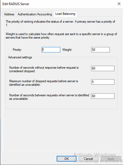
- On the load balancing tab, we must increase some values.
Figure 10: Increment the timeouts to 60 seconds
We need to increase the “Number of seconds without response before request is considered dropped” from 3 to 60 seconds because we have to allow for the extra time it takes to perform the MFA challenge later on. Three seconds is way too small. Also, note that the “Number of seconds between requests when server is identified as unavailable” must be at least the same number of seconds. We don’t set it to a higher value to make sure it does not take too long to detect a downed Server.
- Ensure you don’t forget to add the second RD Gateway server and configure it with the same shared secret and the timeout values.
Figure 11: Both RD Gateway servers added to the RDGWServers group
Also, note the priority of the RD Gateway servers. You can prefer to use one over the other. That way, you have failover but not so much load balancing. That can be useful if you want a predictable path, especially during troubleshooting this comes in handy. Or leave both RDGateway servers at the same priority.
Configuring connection request policies on the NPS Servers
By configuring the RD Gateway to use a central server running NPS to store the RD CAP, the RD Gateway gets configured to forward RD CAP requests to the NPS servers. The NPS servers now process the RADIUS access request. To make the request flow work correctly, you need to create two new policies and verify the policies process in the correct order.
Create the “REQUESTS TOWARDS RD GATEWAY SERVERS” connection request policy
This policy determines when to forward a connection request to one of the RD Gateway servers in the Remote Radius Server group RDGWSERVERS. It needs to be processed first, before “REQUESTS FROM RD GATEWAY SERVERS.”
- On the RD Gateway server, in the “NPS (Local)” console, expand “Policies,” right-click “Connect Request Policies,” and click “New.”
- In the Policy name field, Type ” REQUESTS TOWARDS RD GATEWAY SERVERS.”
- In the “Type of network access server” drop-down list, select “Remote Desktop Gateway.” Then click “Next.”
- In the “Conditions” dialog, click “Add,” select “Day and time restrictions.” Then click “Add.”
- In the “Day and time restrictions” dialog, allow access every day at every hour. Next, click “OK,” then click “Next.”
- In the “Conditions” dialog, click “Add”, select “NAS Port Type”. Then click “Add.”
- In the “NAS Port Type” dialog, check “Virtual (VPN).” Click “OK,” then click “Next.”
- In the Authentication settings, select the option “Forward request to the following remote RADIUS server group authentication, and set it to the “RDGWSERVERS” group.
- In the “Accounting” settings, check the option “Forward accounting requests to this remote RADIUS server group” and select the “RDGWSERVERS” group. Then click “Next.”
- Click “Next” to leave the other settings with their default values. Finally, click “Finish” to create the policy.
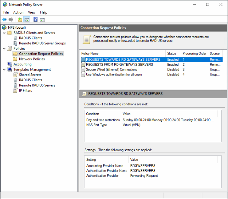
You can check your policy settings in the image below.
Figure 12: REQUESTS TOWARDS RD GATEWAY SERVERS
I usually put the “REQUESTS TOWARDS RD GATEWAY SERVERS” policy first to process on the NPS servers.
Create the “REQUESTS FROM RD GATEWAY SERVERS” connection request policy
This policy determines what to do when you receive a request from one of the RD Gateway servers. I set this policy to process after “REQUESTS TOWARDS RD GATEWAY SERVERS.” See the “Real World Tip” below.
Here we use the client IP address in the conditions and add the IP addresses of the RD Gateway Servers. For good measure, we also add the Client Friendly Name as a condition and add a regex to match the names of our RD Gateway servers. By default, I also always add the “Day and time restrictions” condition and allow access for 24 hours per day. That way, I can adjust this if required to block requests on specific days or during certain hours. Finally, we configure this policy to handle connection requests originating from the RD Gateway servers locally. That is to say, via our local network policies. In the screenshots below, we show how to what values we set these policy settings.
- On the NPS server, in the “NPS (Local)” console, expand “Policies,” right-click “Connect Request Policies,” and click “New.”
- In the Policy name field, Type ” REQUESTS FROM RD GATEWAY SERVERS.”
- In the “Type of network access server” drop-down list, select “Remote Desktop Gateway.” Then click “Next.”
- In the “Conditions” dialog, click “Add,” select “Day and time restrictions.” Then click “Add.”
- In the “Day and time restrictions” dialog, allow access every day at every hour. Next, click “OK,” then click “Next.”
- In the “Conditions” dialog, click “Add,” select “Client IPv4 Address”. Then click “Add.”
- In the “Client IPv4 Address” dialog, type a regular expression like “192\.168\.2\.8[1-2],” uniquely identifying only your two RD Gateway servers. Next, click “OK,” then click “Next.”
- In the “Conditions” dialog, click “Add,” select ” Client Friendly Name.” Then click “Add.”
- In the ” Client IPv4 Address ” dialog, type a regular expression like “RFGW0[1-2],” uniquely identifying only your two RD Gateway servers. Next, click “OK,” then click “Next.”
- In the Authentication settings, select the option “Authenticate requests on this server.”
- In the “Accounting” settings, uncheck the option “Forward accounting requests to this remote RADIUS server group.” Then click “Next.”
- Click “Next” to leave the other settings with their default values. Finally, click “Finish” to create the policy.
You can check your policy settings in the image below.
Figure 13: REQUESTS FROM RD GATEWAY SERVERS
Finally, verify the correct order of the connection request policies
- REQUESTS TOWARDS RD GATEWAY SERVERS (put if first)
- REQUESTS FROM RD GATEWAY SERVERS
- TS GATEWAY AUTHORIZATION POLICY MUST BE DISABLED!
- Use Windows authentication for all users
Move the policies up and down as needed.
| REAL WORLD TIP
Here is a real-world tip for you that can help you notice you did not configure things quite correctly. Assume you set the “REQUESTS FROM RD GATEWAY SERVERS” policy to “Accept users without validating credentials.” The correct setting for this use case is “Authenticate requests on this server.” If you let set the “REQUESTS TOWARDS RD GATEWAY SERVERS” processed secondly, you will be able to log in, but without enforcing the RD CAP. Meaning the device redirection policy where you block specific devices (drives, printers, clipboard, …) does NOT kick in. However, when you process “REQUESTS TOWARDS RD GATEWAY SERVERS” is first, the CAP is enforced. But you let the allow “Accept users without validating credentials” in the “REQUESTS FROM RD GATEWAY SERVERS” slip through!. So, mind the correct order and the correct configuration of the policies. They matter a lot! |
Create and configure the network policy (RD CAP) on the NPS servers
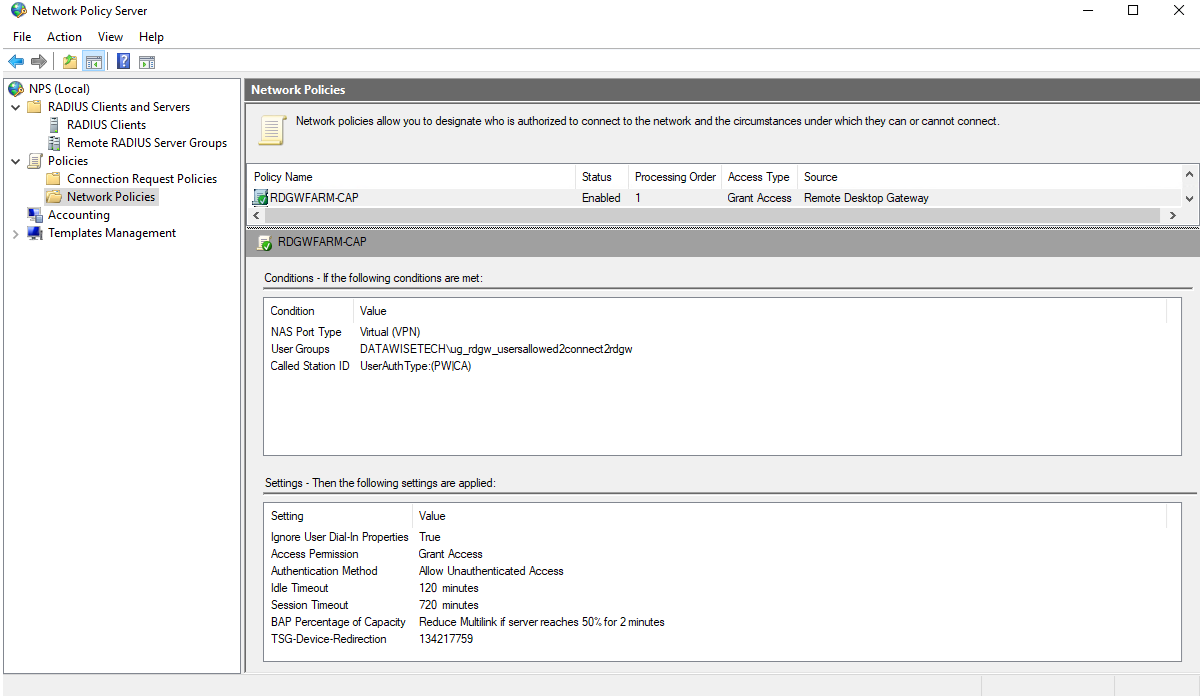
Finally, we need to create our network policy. This one performs the function of the RD CAP as you have locally on your RD Gateway when you are not using a remote NPS Server. That means you can copy the settings from the NPS GUI locally on an RD Gateway server. That’s the easiest way to do it, and you will recognize the RD CAP settings in there.
As you can see, we have a universal group in Active Directory that contains users who are allowed to connect to the RD Gateway server. Membership gets validated against Active Directory when authenticating the user, but NPS itself does no authentication. That is why your will notice “Allow Unauthenticated Access” has to be set in the allowed authentication methods.
We have adapted the idle and session timeout values. These will differ per policy based on user, location, and security needs.
Figure 14: The network policy on the NPS server contains the conditions that make up an RD CAP.
Pay extra attention to the value of TSG-Device-Redirection vendor-specific. This value determines your device redirection settings, what to block or what to allow. The easiest way to find out the needed value is to configure it on an RD Gateway with a local NPS server and copy the value. You already have those on your existing RDGW servers, so copy it from there.
I disable device redirection for all client device types. That still allows for smartcard readers and such to work. I also tick the “Only allow client connections to Remote Desktop Session Host servers that enforce RD Gateway device redirection” check box. All that translates into 134217759 for the TSG-Device-Redirection Attribute. Of course, you can always calculate it yourself using this information.
That’s it for our first NSP server, NPS01. We can now export the configuration and import it onto the second NPS server, NPS02. That’s a lot easier and less error-prone than configuring all this again manually.
Changing the configuration on RDGW02
Remember that we need to switch to a central server running NPS. The process to minimize service interruption is as follows.
Disable one RD Gateway server (RDGW02) on the KEMP Loadmaster. Doing so can impact existing connections on RDGW02. That depends on how the load balancer handles drain times, existing sessions, and how long you wait before starting work on RDGW02. The good news is that an RDP session will renegotiate and reconnect to the other RD Gateway server (RDGW01), which handles requests during the transition.
We use RDGW02 to test our setup changes and confirm that they work. Then, when all is well, we can switch over and take RDGW02 in production by enabling RDGW02 and disabling RDGW01 in the Kemp LoadMaster. We then configure it precisely like RDGW02, test it, and if all is well, we bring it back into production by enabling it again in the Kemp LoadMaster.
Note: for testing, you need to bypass DNS, taking you to the load balancer VIP for this service. We do this by adding an entry to the host file of the test client where telecommute.datawisetech.corp points to the IP of RDGW02. Any other client will still follow DNS and hit the load balancer that sends them to RDGW01, serving requests in production while you transform RDGW02.
Move to a central server running NPS
In the RD Gateway GUI, right-click your RD Gateway server and select properties. Next, navigate to the RD CAP Store tab. There you select “Central server running NPS.”
Figure 15: Swap to a Central server running NPS and add the NPS servers
Figure 16: Enter the shared key we created before for the NPS servers
Add both NPS Server their FQDNs to the list of NPS servers. Note that you must enter the shared secret you used on the NPS servers. You can alter the order of the NPS servers for testing one in particular or to balance requests. Clicking “Apply” or “OK” here tends to take a while, and the GUI might become unresponsive before it reacts again. The GUI location where it used to say “Connection Authorization Policies” will now show “Central Network Policy Servers,” which list the NPS servers you added.
Note that the “Connection Authorization Policies” still exist in the local NPS setting of the RD Gateway server. So we can always take a peek there for the settings. Also, if we ever revert them to “local server running NPS,” the policies will still exist.
As mentioned before, we are adding two NPS servers for redundancy. Also, if for some reason you need to revert to a local NPS / RD CAPs, the policies are still there.
Configure the local NPS server setting on the RD Gateway server
Configure RADIUS client on RD Gateway NPS
Now we will define both NPS servers as RADIUS clients on RDGW02. That way, communication NPS servers can communicate with the RADIUS/NPS server on the RD Gateway server.
- On RDGW02, open Server Manager, click Tools and then click Network Policy Server. Next, in the NPS (Local) console, expand RADIUS Clients and Servers, right-click RADIUS Clients, and finally click New.
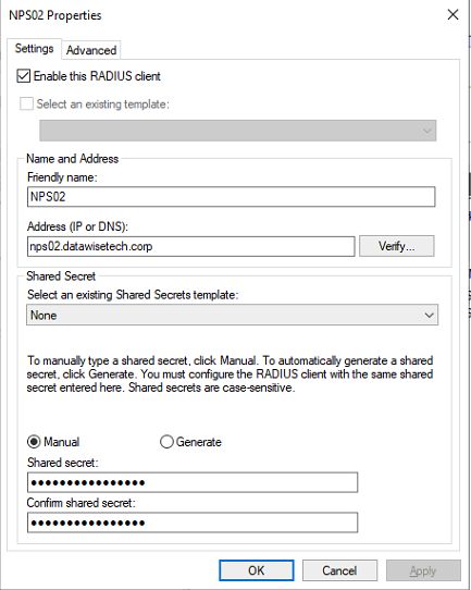
- On the Settings tab, provide a Friendly Name. I use the hostname of the NPS server. In the Address (IP or DNS) field, type the FQDN of the NPS server. Click Verify to ensure that the FQDN can be resolved and click OK.
- In the Shared secret field, type the same shared secret we used before. Click OK.
Figure 17: Adding an NPS Server as a RADIUS client on the RD Gateway server.
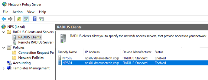
- Repeat this process for the second NPS server, NPS02. Again, you need to add both of them.
Figure 18: Add both NPS servers as RADIUS clients on the RD Gateway server
Configure Remote RADIUS Server setting on RD Gateway NPS
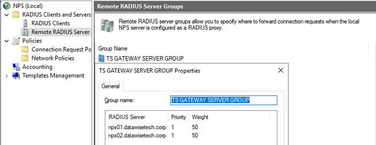
- Open the NPS GUI, expand “RADIUS Clients and Servers,” select “Remote RADIUS Server Groups.” Then, open the “TS GATEWAY SERVER GROUP.”
- You should see the NPS servers you added when you configured the RD Gateway server to use central NPS servers in this group.
WARNING! Do NOT change the name of this group to something else like “NPSSERVERS.” Contrary to some advice on the Internet, that’s not a great idea. The RD Gateway role & GUI expects the original group name to exist. So after a reboot, you might find yourself with an empty, freshly created empty “TS GATEWAY SERVER GROUP.”
Meanwhile, in the RD Gateway GUI, you cannot see the NPS servers even with the connection request policies still configured for central NPS servers. That will ruin the day for your end-users and yourself. They’ll be calling you while you try to figure out what happened!
Figure 19: The TS GATEWAY GROUP contains both NPS servers you added when configuring central servers running
- Select FQDN of every NPS server and click Edit.
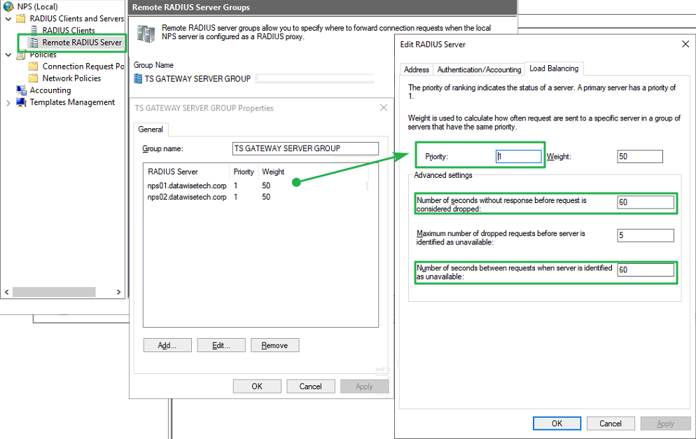
- Navigate to the Load Balancing tab. As we did before on every NPS server in the Load Balancing tab, we need to increase the “Number of seconds without response before request is considered dropped” from 3 to 60 seconds. We do so to allow for the extra time it takes to perform the MFA challenge later on. Three seconds is way too. If you leave it at three seconds, RD Gateway will fail before you even get your MFA challenge, let alone complete it. Also, note that the “Number of seconds between requests when server is identified as unavailable” must be at least the same number of seconds. We chose this as low as possible to make sure it does not take too long to detect a downed Server.
Figure 20: Configure RADIUS timeout value on RD Gateway NPS
Also, note the priority of the NPS servers. You can prefer to use one over the other. That way, you have failover but not so much load balancing. Unless you reverse the priority on the second RD gateway server, preferred priorities can be helpful if you want a predictable path. Especially during troubleshooting, this comes in handy. When you set both NPS Servers at the same priority, it will alternate between the two.
Configure connection request policies on the RD Gateway local NPS server settings
By configuring the RD Gateway to use a central server running NPS to store the RD CAP, the RD Gateway gets configured to forward RD CAP requests to the NPS servers. The NPS servers now process the RADIUS access request. To make the request flow work correctly, you need to create two new policies, disable the existing “TS GATEWAY AUTHORIZATION POLICY,” and verify the policies process in the correct order.
Create the “REQUESTS FROM CENTRAL NPS SERVERS” connection request policy
This policy determines what to do when you receive a request from one of the NPS servers. This policy needs to be processed first before “REQUESTS FROM CENTRAL NPS SERVERS.”
- On the RD Gateway server, in the “NPS (Local)” console, expand “Policies,” right-click “Connect Request Policies,” and click “New.”
- In the Policy name field, Type ” REQUESTS FROM CENTRAL NPS SERVERS.”
- In the “Type of network access server” drop-down list, select “Remote Desktop Gateway.” Then click “Next.”
- In the “Conditions” dialog, click “Add,” select “Day and time restrictions.” Then click “Add.”
- In the “Day and time restrictions” dialog, allow access every day at every hour. Next, click “OK,” then click “Next.”
- In the “Conditions” dialog, click “Add,” select “Client IPv4 Address”. Then click “Add.”
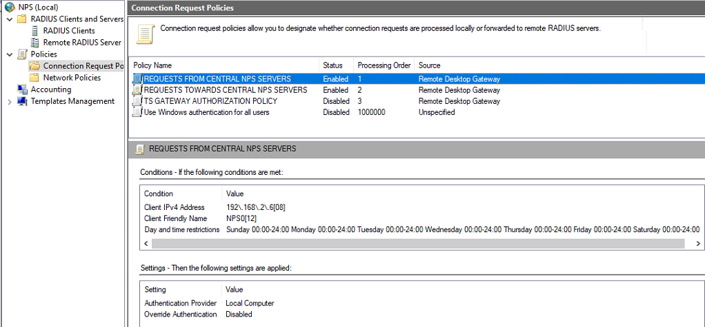
- In the ” Client IPv4 Address ” dialog, type a regular expression like “192\.168\.2\.6[08],” uniquely identifying only your two NPS Servers. Next, click “OK,” then click “Next.”
- In the “Conditions” dialog, click “Add,” select ” Client Friendly Name.” Then click “Add.”
- In the ” Client IPv4 Address ” dialog, type a regular expression like ” NPS0[12], ” uniquely identifying only your two NPS Servers. Next, click “OK,” then click “Next.”
- In the Authentication settings, select the option “Authenticate request on this server”, then click “Next.”
- Click “Next” to leave the other settings with their default values. Finally, click “Finish” to create the policy.
You can check your policy settings in the image below.
Figure 21: REQUESTS FROM CENTRAL NPS SERVERS policy settings
Create the “REQUESTS TOWARDS CENTRAL NPS SERVERS” connection request policy
This policy determines when to forward a request to one of the NPS servers. This policy needs to be processed secondly right after “REQUESTS FROM CENTRAL NPS SERVERS.”
- On the RD Gateway server, in the “NPS (Local)” console, expand “Policies,” right-click “Connect Request Policies,” and click “New.”
- In the Policy name field, Type “REQUESTS TOWARDS CENTRAL NPS SERVERS.”
- In the “Type of network access server” drop-down list, select “Remote Desktop Gateway.” Then click “Next.”
- In the “Conditions” dialog, click “Add,” select “Day and time restrictions.” Then click “Add.”
- In the “Day and time restrictions” dialog, allow access every day at every hour. Next, click “OK,” then click “Next.”
- In the “Conditions” dialog, click “Add”, select “NAS Port Type”. Then click “Add.”
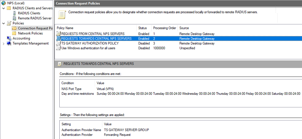
- In the “NAS Port Type” dialog, check “Virtual (VPN).” Click “OK,” then click “Next.”
- In the Authentication settings, select the option “Forward request to the following remote RADIUS server group authentication, and set it to the “TS GATEWAY SERVER GROUP” group.
- In the “Accounting” settings, many people check the option “Forward accounting requests to this remote RADIUS server group” and select the “TS GATEWAY SERVER GROUP” group. Then click “Next.” I uncheck this option as it stops the Azure MFA logs from being inundated with errors and information messages due to the NPS Extension for Azure MFA not handling these.
- Click “Next” to leave the other settings with their default values. Finally, click “Finish” to create the policy.
You can check your policy settings in the image below.
Figure 22: REQUESTS TOWARDS CENTRAL NPS SERVERS policy settings
Finally, verify the correct order of the connection request policies
- REQUESTS FROM CENTRAL NPS SERVERS → Has to be first, or you’ll never get the answer from the NPS server back and won’t be able to log in.
- REQUESTS TOWARDS CENTRAL NPS SERVERS
- TS GATEWAY AUTHORIZATION POLICY → MUST BE DISABLED!
- Use Windows authentication for all users
Move the policies up and down as needed.
Testing the configuration changes on RDGW02
RDGW02 is the RD Gateway server we took out of production by disabling it on the load balancer. We did so to ensure we can work safely on this one while RDGW01 hands the production requests. In addition, on a test client, we add an entry for the VIP of the RD Gateway services on the load balancer to the C:\Windows\System32\drivers\etc\hosts file. That way, we bypass DNS and test the functionality. If you configured everything correctly, you should be able to pass the RD CAPs and RD RAPs as before via RDGW02, sending you to either NPS01 or NPS02 for evaluation of the RAP.
When all is working correctly, we take RDGW02 into production by enabling it on the load balancer.
Change the configuration on RDGW01
We do a rinse & repeat of the above, but now for the second RD Gateway server. Disable RDGW01 on the load balancer, and we will make the changes to RDGW01 while RDGW02 handles requests in production.
When we have configured and tested RDGW01, just as we explained for RDGW02 as described above, we bring that one into production by enabling it on the load balancer, and voila, both our RDGW servers are now leveraging our two NPS servers.
Finally, on the test client, remove the entry for the VIP of the RD Gateway services on the load balancer from the host file. Test by connecting to a computer via the RD Gateway. That is a final verification of your production environment. Your users should not notice anything different.
For many people moving to a central server running NPS is the trickiest part to get right. With this behind us, we can leave it be for a while to see if it works correctly over time. Then, we are ready for phase II, where we add the NPS Extension for Azure MFA to the authentication process.
