Introduction
I often need a firewall for testing and lab work to validate designs in more realistic ways and set up VPNs for cloud providers. Proprietary firewalls are expensive, and most of the time, you cannot update them without a paid subscription or when the device model is “end of life,” no longer supported, and receives no more updates. That is why I run OPNsense in my labs. You can download the open-source OPNsense ISO’s here. I run it on a Hyper-V, which works very well. OPNsense provides me with a cost-effective and capable firewall in the lab or in production where applicable.
Types of VPN site-to-site configurations
There are three main site-2-site IPSec VPN configurations we can set up with OPNsense and Azure Virtual WAN:
- Policy-based OPNsense Site-2-Site VPN (Part 1)
- Route-based OPNsense Site-2-Site VPN (Part 2)
- Route-based with BGP OPNsense Site-2-Site VPN (Part 3)
In part 1, I showed you how to configure a policy-based site-to-site VPN between Azure and OPNsense. Part 2 is about how to set up a route-based site-to-site VPN between Azure and OPNsense without BGP. You are reading part 3, where I show how to set up a route-based site-to-site VPN between Azure and OPNsense with BGP. While BGP is nice, remember that a route-based site-to-site VPN with static routes works well for many of us who run smaller networks and when you need to control routing down to the last detail. That said, you can achieve the same with BGP if configured correctly.
Using BGP with two active-active tunnels on both sides imposed some requirements on the on-premises appliance. That boils down to whether that appliance can run BGP over two tunnels over one public IP address. If not, we need a second public IP address on a second WAN interface. Like CISCO ASA, WatchGuard, PFsense, and others, OPNsense does not support looping back to both BGP peering addresses in Azure over a single public IP. My Barracuda Cloud Generation firewall appliance can do this and offers two tunnels via a single public IP address. But we cannot play that game here. So, I added a second WAN interface, which grabs a second public IP from my ISP.
There needs to be more 100% complete documentation about setting up an OPNsense VPN to an Azure Virtual WAN VPN Gateway. In contrast to the policy-based and static route-based site-to-site VPNs, BGP tunnels with OPNsense have different requirements to get working compared to pfSense. So, I hope my sharing with you how I do my setups is helpful.
If you wonder, yes, you configure BGP on your Azure VWAN VPN Gateway, which always provides two active-active tunnels. See Tutorial: Create site-to-site connections using Virtual WAN. However, you can connect to a single appliance with active-active tunnels without using BGP, depending on how you configure the VPN Site itself on the VPN gateway in Azure. These are the policy-based and route-based configurations. I also show you what you need to do on the Azure side to make this work. You need a second OPNsense appliance for complete redundancy, which requires using BGP. That is beyond the scope of this. Also, note that OPNsense has active-passive HA.
Note: I have changed the actual public IP addresses used in the article for the screenshots, and where those IPs are visible in screenshots, I have masked them.
- x.x.x.x = Public IP Instance 0 of Azure VWAN VPN Gateway
- y.y.y.y = Public IP Instance 1 of Azure VWAN VPN Gateway
- z.z.z.z = Public IP (WAN) on-premises OPNsense firewall
- w.w.w.w = Public IP (WAN2) on-premises OPNsense firewall
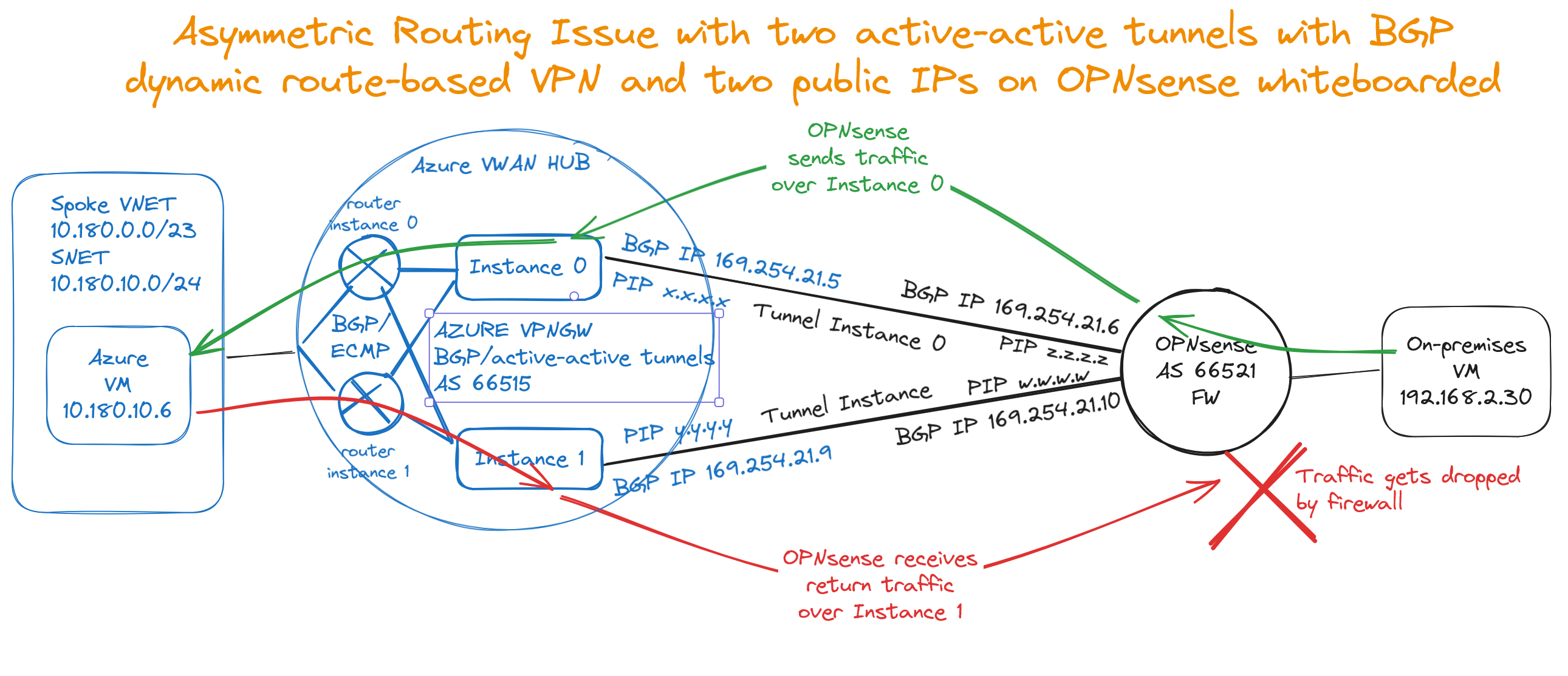
I refer you to the image below for an overview of what we are building.
On the Azure VWAN VPN Gateway
If you have read the previous parts, this is partially the same but contains all the settings relevant to BGP. Do NOT skip this section!
For this post, I do not repeat how to deploy resource groups, networking, virtual machines, an Azure Virtual WAN with a Virtual Hub, connected VNEts, and a VPN Gateway. That has been done before and well by Microsoft. I point out the subtle difference we need to configure when creating a VPN site for policy-based or route-based site-to-site VPN versus one for routed-based with BGP, for example.
Configure APIPA BGP IP addresses
I need to leverage APIPA BGP IP addresses to get a dynamic route-based site-to-site VPN with Azure to work in combination with OPNsense. That differs from how I do it in pfSense or on a Barracuda cloud generation firewall. So, I struggled a bit with this one at first.
 I added two /30 subnet IP addresses per VPN instance. That is because I want two active-active tunnels per OPNsense appliance, and I need two OPNsense appliances for redundancy.
169.254.21.4/30 169.254.21.5 (Azure) and 169.254.21.6 (OPNsense)
169.254.21.24/30 169.254.21.25 (Azure) and 169.254.21.26 (OPNsense)
169.254.21.8/30 169.254.21.9 (Azure) and 169.254.21.10 (OPNsense)
169.254.21.28/30 169.254.21.29 (Azure) and 169.254.21.30 (OPNsense)
Azure VPN gateways use a reserver APIPA address range from 169.254.21.0 to 169.254.22.255, so we selected these /30 subnets. See Configure BGP for VPN Gateway
Why do I use /30 subnets? Because that is how OPNsense handles (APIPA) BGP IP address ranges. It also gives you a clue as to why it does not work with the defaults of 10.252.250.12 and 10.250.250.13 for the instances, as these are in the same /30 subnet. Also, to have two active-active tunnels on a single OPNsense appliance, I need to use two public IP addresses on the on-premises side per appliance, for which I need more BGP IP addresses than the default provides.
You can download the VPN config file from the portal quite easily.
You can find the public addresses for your VPN tunnel instances in that file. Information about the connected VNETs and, depending on the type of VPN sites you configured, the private IP address for your VPN tunnel instances and BGP ASN number are also there. It has everything you need to configure your VPN. In case you need to find out what ASN number you can use in Azure and on-premises, see the Azure VPN Gateway FAQ
Create an Azure VWAN VPN site
When you create a VPN site, please name it and specify the vendor as always, but with BGP, do not enter the private address space you want to connect to. BGP takes care of all this.
Once you have done that, you must create at least one link. Name it, provide the link provider name, and add the link speed. Finally, add your on-premises firewall’s remote IP address or FQDN (z.z.z.z on the overview image). Also, provide the Link BGP address (169.254.21.6) and ASN number (65521).
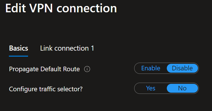
When connecting the policy-based VPN site to your Virtual Hub, ensure that “Configure traffic selector” is set to No.
Notice that I enabled BGP for the link connection settings. Ensure that you use IKEv2 and, very importantly, verify that the “Use policy-based traffic selector” is disabled. You must take care of these details when setting up the VPN site, link, and connection to the Virtual Hub.
As an extra learning moment, let’s use a custom IPSec policy. I left that as an exercise for the reader in parts 1 and 2 of this series. Here, I show you how to do it. I also changed the SA lifetime to 27000 instead of the default and recommended 28800 (8 hours). I am just showcasing the options. Refer to your appliance vendor docs for guidance on what they recommend. I refer you to Virtual WAN site-to-site IPsec policies for Microsoft’s advice. Please read it. It is essential for security, performance, and, as such, scalability.
OPNsense firewall configuration for IPYSec
Below is a partial repeat if you have read parts 1 or 2.
If you made it this far in the article, you know how to install an OPNsense device. If not, grab the image and deploy it in a virtual machine to practice. There are plenty of good articles on how to do this all over the internet. Come back when you have that covered 
First, we must allow IPsec tunnel connections over the OPNsense WAN interface. Add the following rules under Firewall/Rules/WAN. Now, unless you turn off the automatic firewall rules creation, you should have those rules configured for you. Even when then, it pays to be explicit about them. If they are not, don’t forget to add them!
- Protocol ESP
- UDP Traffic on port 500 (ISAKMP)
- UDP Traffic on port 4500 (NAT-T)
Pro Tip: use an alias in which you collect all remote IP addresses (x.x.x.x and y.y.y.y) that can initiate an IPSec connection to your OPNsense firewall. Since we have two active-active tunnels with Azure VWAN, reducing the number of rules to add already pays off. Maintenance is also a lot easier.
OPNsense firewall IPSec rule to allow traffic from Azure
We must add an extra firewall rule to the IPSec interface for route-based traffic to flow from Azure to on-premises. Navigate to Firewall/Rules/IPSec. Add a rule to allow traffic from your Azure network, 10.180.0.0/16 in this example, to your on-prem network, VLAN2 net. You can use an alias to group IPs/networks to keep your rules manageable. But this is a simple lab example.
Remember this, or traffic originating from Azure drops at the OPNsense firewall before reaching the local network. You also have firewalls on hosts, NGG rules, and possible NVAs in Azure that might also come into play. Remember those; many moving parts must align to work correctly!
Dynamic (BGP) route-based OPNsense Site-2-Site VPN Setting
We now discuss configuring OPNsense with a route-based site-to-site VPN leveraging dynamic routing via BGP.
Above, in preparation, I already configured the OPNsense firewall to allow IPSec from Azure. In Azure, I configured a BGP-based VPN site with a link configured to leverage dynamic routing via BGP.
First, if you have any policy-based or static route-based phase 1 VPN tunnels to your VPN gateway, deactivate those. Doing so avoids conflicting settings, not to mention confusion. You could also delete them.
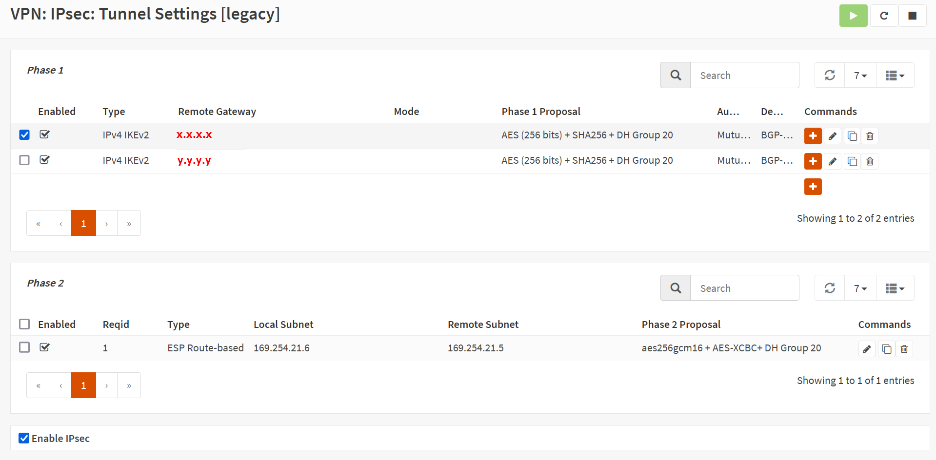
In OPNsense, navigate to VPN/IPsec/Tunnel Settings [legacy] and create a new Phase 1 entry using the + button. Fill out or change the information as shown below. Green are values I changed, and you can use them. Purple means you MUST replace it with the values for your environment.
Again, I show the configuration for one tunnel, instance 0. of the Azure VWAN site-to-site VPN. You should repeat the process for tunnel instance 1 to get failover/redundancy during maintenance in Azure. For full redundancy, you need a second OPNSense appliance, but that is beyond the scope of this article.
Phase 1
General Information
Disabled: unchecked
Connection method: Start immediate
Key Exchange version: V2
Internet Protocol: IPv4
Interface: WAN
Remote gateway: x.x.x.x
Dynamic gateway: unchecked (Allow any remote gateway to connect)
Description: BGP-PHASE1-INSTANCE0-AZURE-VWAN
The IP address for the Remote gateway, x.x.x.x, is the Azure VPN Gateway – Instance 0 Public IP. Setting up Instance 1 is an exercise for the reader, and use the IP address of Instance 1.
The screenshot below is for your reference.
Proposal (Authentication)
Authentication method: Mutual PSK
My identifier: My IP address
Peer identifier: Peer IP address
Pre-Shared Key: YOUR COMPLEX SHARED KEY STRING
The screenshot below is for your reference
Proposal (Algorithms)
We use the Azure VPN gateway defaults here for encryption and hashing algorithms. These are known to work at the time of writing. Microsoft has recommendations on what is better and more performant. There is an option to customize this in the Azure site-to-site VPN settings. I leave that as an exercise for the reader and for when the organization mandates it.
Encryption algorithm: AES
256
Hash algorithm: SHA256
DH key group: 20 (NIST EC 384 bits)
The screenshot below is for your reference
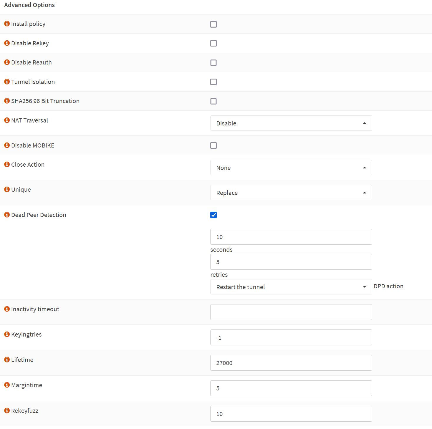
Advanced Options
Install policy: unchecked
Disable Rekey: unchecked
Disable Reauth: unchecked
Tunnel Isolation: unchecked
SHA256 96 Bit Truncation: unchecked
NAT Traversal: Disable
Disable MOBIKE: unchecked
Close Action: None
Unique: Replace
Dead Peer Detection: checked
10 seconds
5 retries
Restart the tunnel DPD action
Inactivity timeout
Inactivity timeout: unchecked
Keyingtries: empty
Lifetime: 27000
Margintime: empty
Rekeyfuzz: empty
Take Note
Make sure to UNCHECK the “Install policy” option. We use routes, not policies, so you cannot enable this here.
The screenshot below is for your reference.
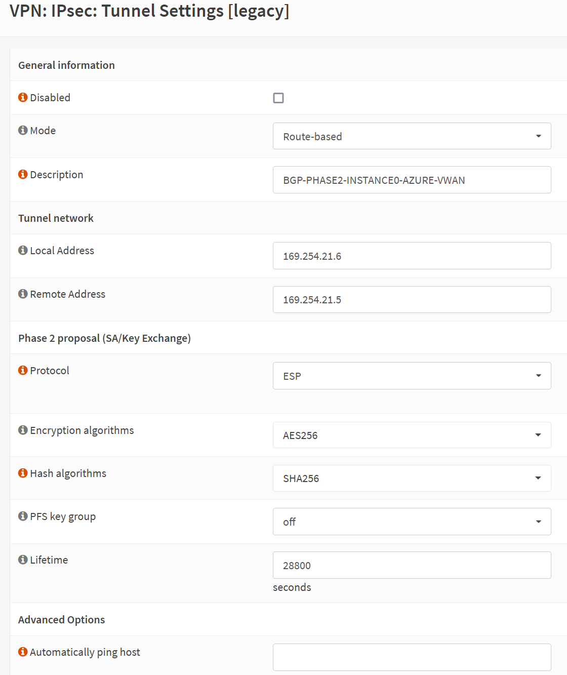
Phase 2
General information
Disabled: unchecked
Mode: Route-based
Description: BGP-PHASE2-INSTANCE0-AZURE-VWAN
Phase 2 Tunnel network
Local Address: 169.254.21.6
Remote Address: 169.254.21.5
Phase 2 proposal (SA/Key Exchange)
Protocol: ESP
Encryption algorithms: AES256
Hash algorithms: SHA256
PFS key group: off
Lifetime: 27000 (seconds)
We use APIPA addresses, which we don’t use for anything else anywhere, for the local and remote addresses in the tunnel network. In Azure, you can optionally configure these, which we did earlier in this article, as this is the only way we can get BGP working between OPNsene and Azure.
As a reminder, 169.254.21.5 is the APIPA BGP IP address we set in Azure for the instance-0 tunnel. OPNsense works with APIPA addresses in a /30 network. That means we need to use 169.254.21.6 on the OPNSense side of things.
Let’s explain the /30 (255.255.255.252) subnet logic again here. When we take 169.254.21.4/30, that gives us two usable IP addresses in this APIPA subnet. Those are 169.254.21.5 and 169.254.21.6 for tunnel instance 0. We use 169.254.21.5 in Azure and use 169.254.21.6 in our OPNsense.
We have two tunnel instances, and for the instance-1 tunnel, we used 169.254.21.9 in Azure, so on OPNsense, we must use 169.254.21.10.
Phase 2 Advanced Options
Automatically ping host: empty
The screenshot below is for your reference.
We have completed the VPN tunnel setup for Instance 0. We need to finish the rest of the OPNsense configuration to make the BGP, dynamic route-based site-to-site VPN work.
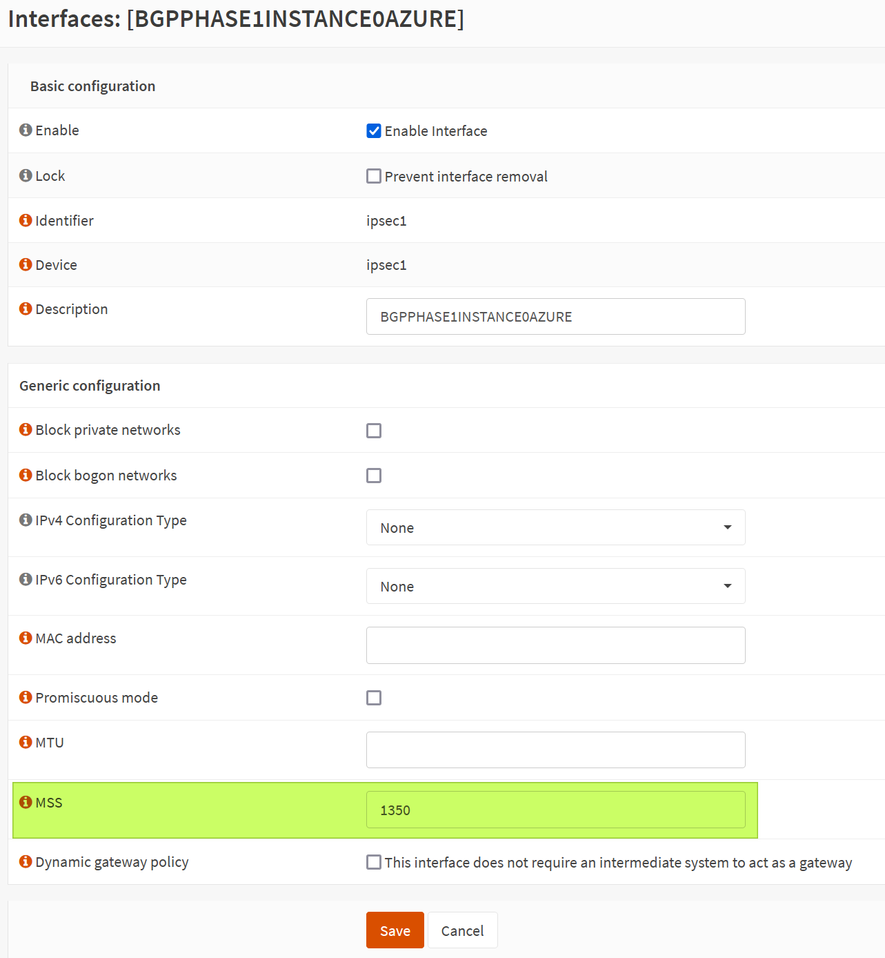
Set MSS size
Under Interfaces for your automatically created IPSec interface, set the MSS value to 1350. Remember this. Leave all the other settings on their default value.
MSS stands for Maximum Scale Size. See https://docs.opnsense.org/manual/firewall_scrub.html for more information.
The screenshot below is for your reference.
Rinse and repeat for Instance 1
I showed how to set up the first VPN tunnel for Instance 0. Repeat that process with the input for Instance 1, and when done, you should see two tunnels with their respective phase 1 and phase 2 settings configured.
Do I need to add a gateway for the VPN tunnel’s interface?
No! With BGP, there is no need to add a gateway for your VPN tunnel’s interface. Routing is taken care of by the FRR/BGP configuration. That differs from a static-route site-to-site VPN tunnel we discussed in part 2. BGP is dynamic routing, which brings us to the next question.
Do I need a static route (via a gateway) to the Azure address space(s)?
First, you do not need a gateway, as mentioned above. So, there is no need for static routes. Second, If you have a gateway and must create static routes to reach Azure subnets, there is an issue with the BGP configuration!
One such example is that if your BGP routes are marked invalid, it does not inject them into the routing table. You can work around that by creating static routes. But, to be clear, that’s a workaround but not the solution.
You can see an example of such an issue below. I had set up a dynamic-route (BGP) site-to-site tunnel on OPNsense as we did for pfSense, but that does not work! In pfSense, we do not need APIPA addresses and mandatory /30 subnet IP ranges for the tunnel and BGP. In OPNsense, we do. A workaround to get the below to work would be adding static routes, but that is cheating. 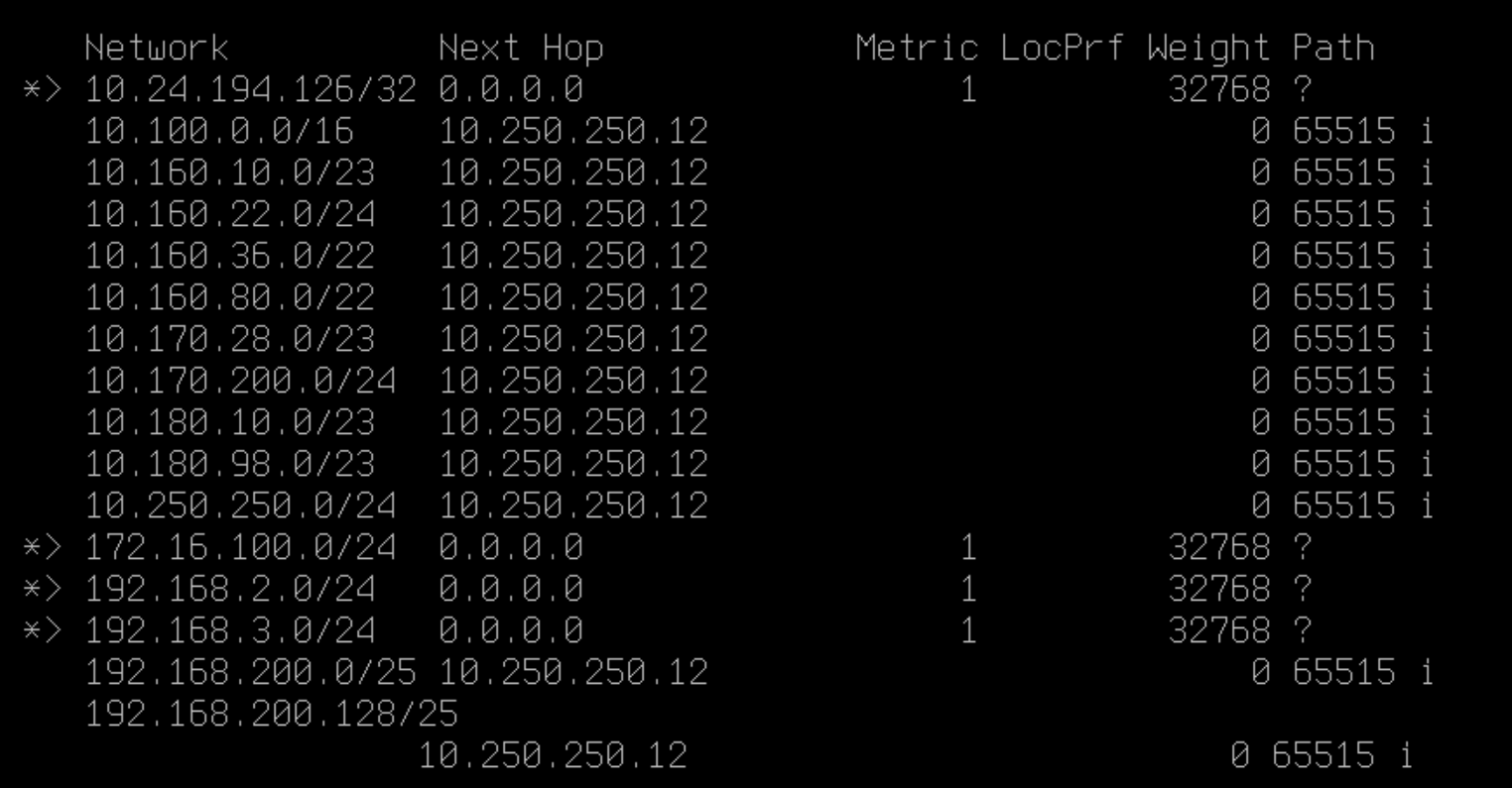
Configuring BGP for dynamic routing
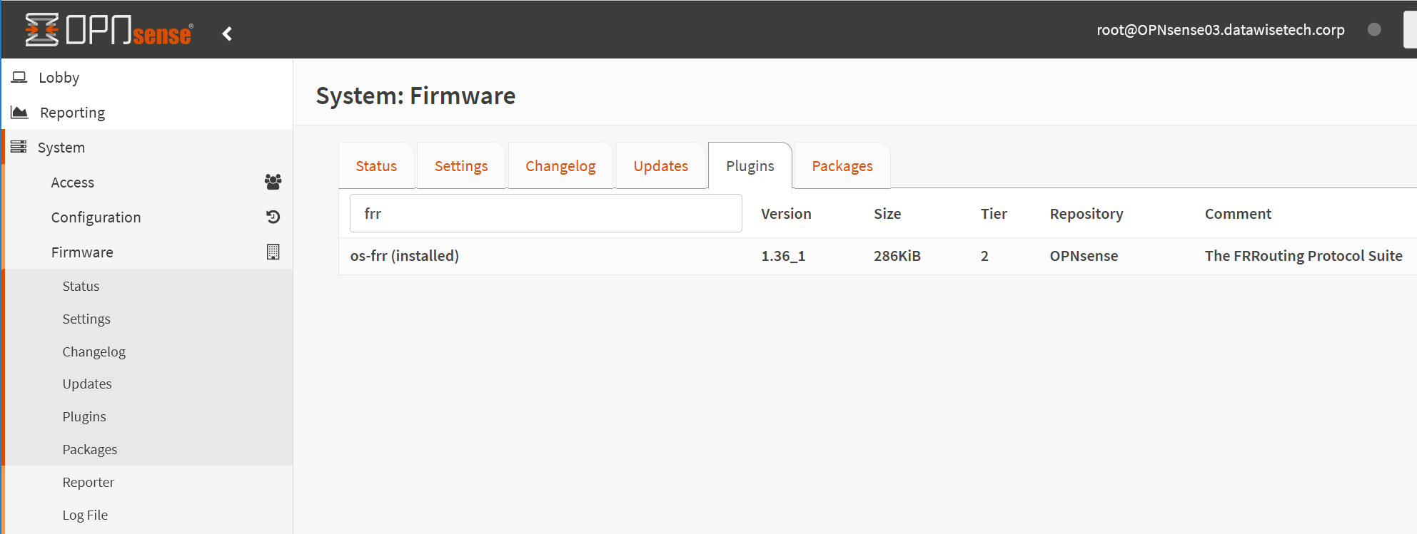
frr plugin installation
FRRouting (FRR) is an open-source Internet and free routing protocol suite for Linux, Unix, and Open BSD platforms. With this plugin, OPNsense supports BGP and BFD, as well as OSPF, OSPFv3, and RIP.
How?
In OPNSense, select System > Firmware > Plugins, search for “FRR” and click + to install:
Enable BGP
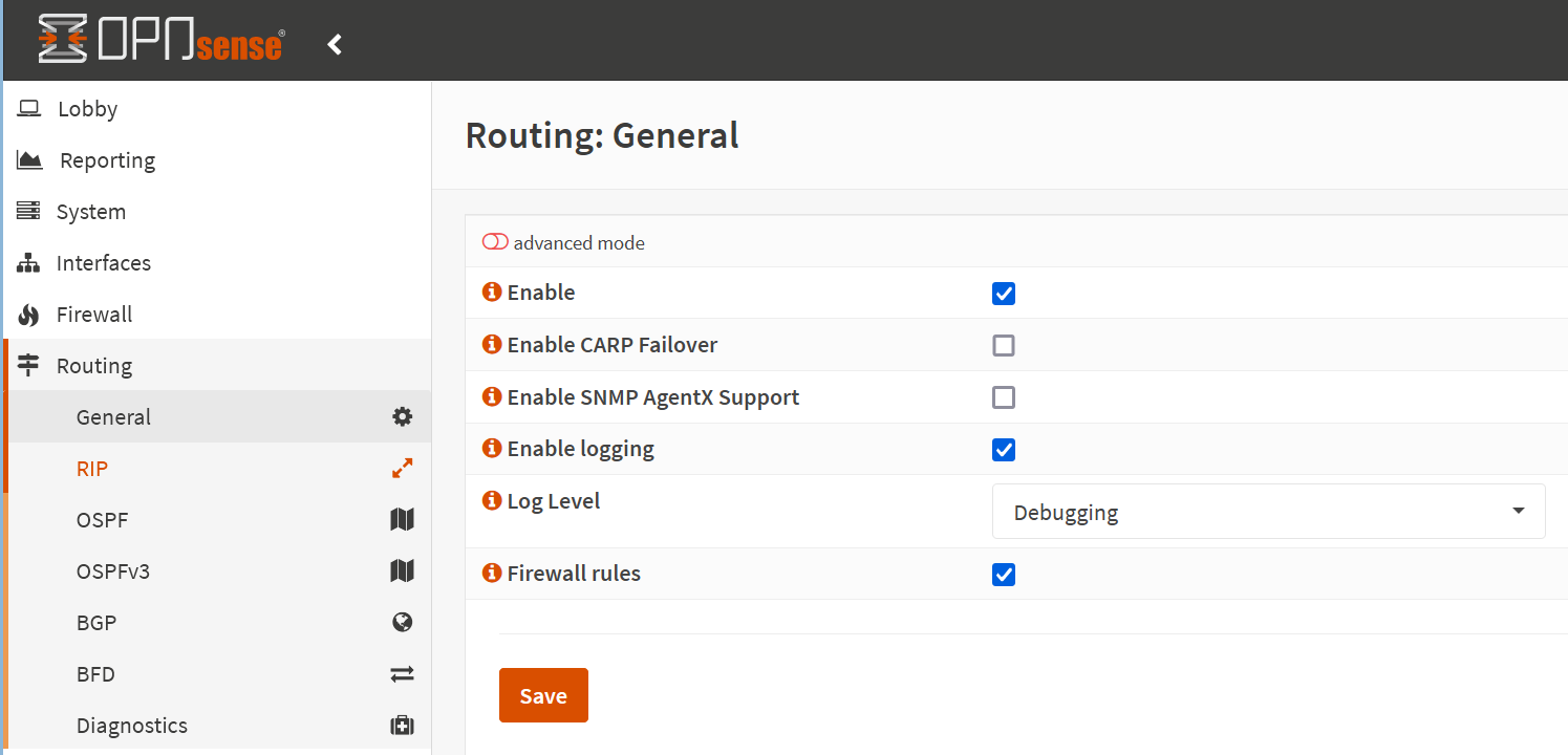
With the FRR package installed, refresh the OPNsense browser GUI, and you’ll find a new entry named “Routing” in the left navigating pane. Open it, navigate to “General,” and enable it. Also, enable logging. For setup and troubleshooting, I chose Debugging for the logging level. I set that back to “after everything is configured and tested. Leave “Firewall rules” enabled, as that helps you by creating the needed firewall rules for you. Nonetheless, I do point out essential rules explicitly.
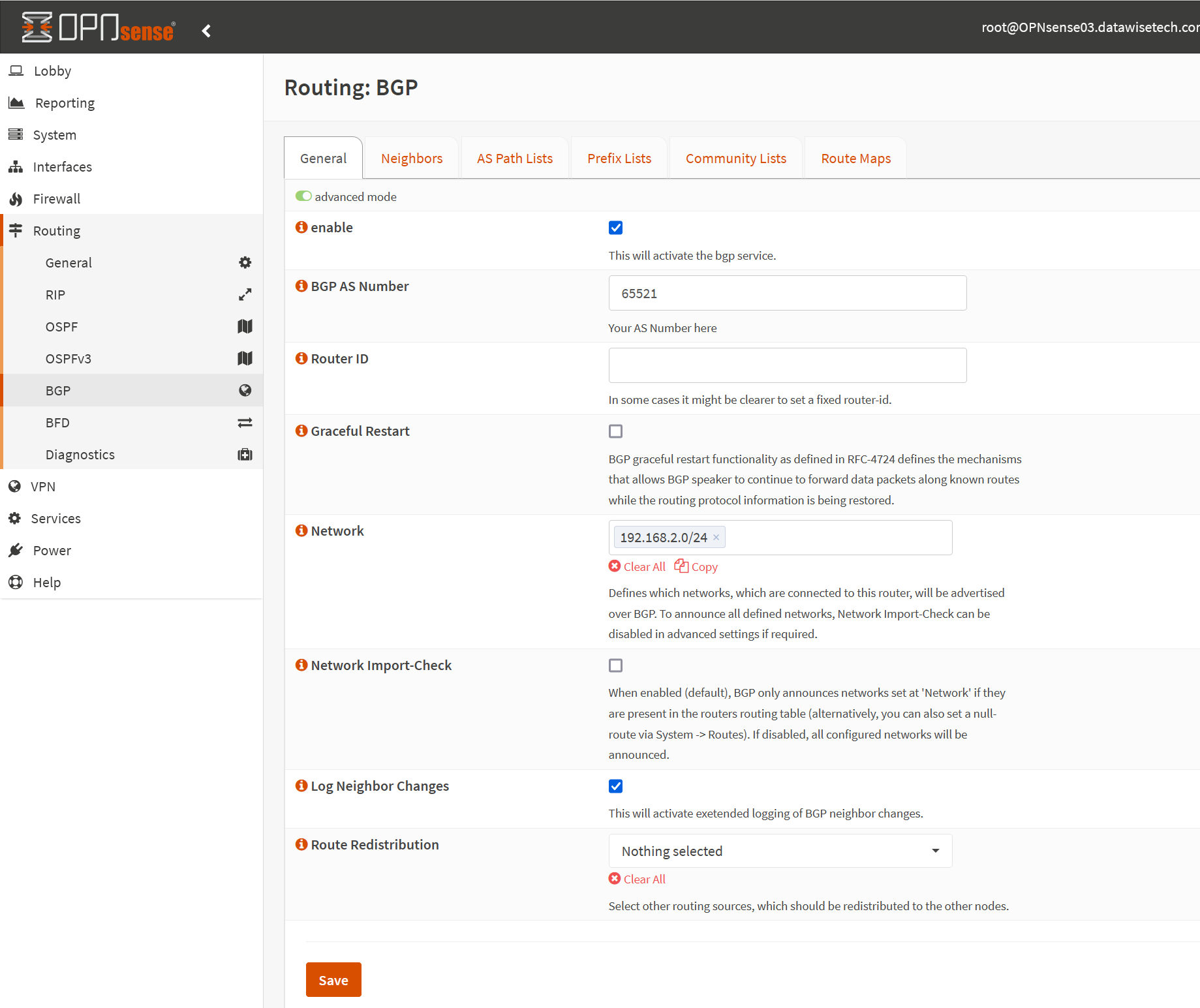
Now navigate to “BGP” in the left pane. Enable “Advanced mode.
- Enable BGP
- Fill out the BGP AS Number (65521)
- Enter the subnets you want to advertise under “Network.” That is how you can be very selective in what on-prem networks you allow to propagate over the VPN tunnel.
- Enable “Log Neighbors Changes”
We leave the rest at their defaults. The Rouder ID must be unique between BGP peers but can be left empty. We could set it to one of our Public IPs here.
Set up Prefix-Lists
Select the “Prefix Lists” tab and click “+” to add lists. I created two basic ones.
The first, with sequence number 9, blocks the default route from being propagated.
The second, with sequence number 10, allows all other prefixes.
Configuring AS
Securing your BGP
We want to ensure our OPNsense AS router does not send unwanted network prefixes to neighbor AS routers. On the other hand, we do not wish to receive unwanted network prefixes from neighbor routers either. To achieve this, we can filter on ASNs that our OPNsense appliance can send or receive network prefixes to and from. For this, we use BGP AS Path Filters.
BGP AS Path Filters
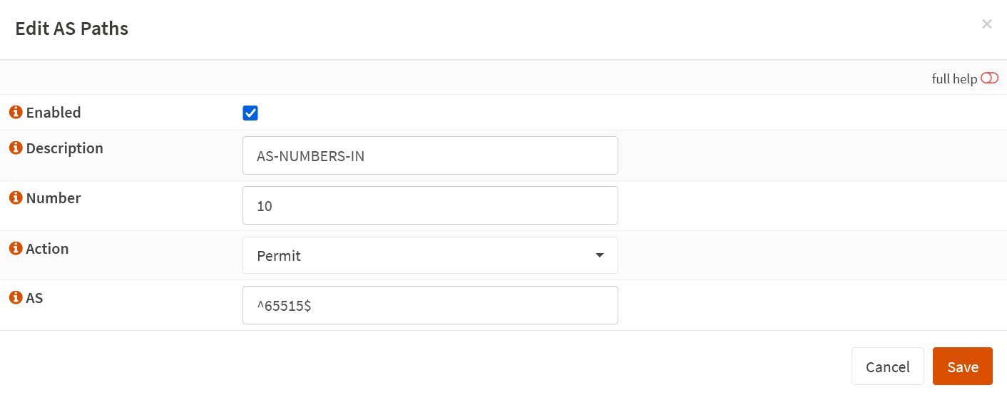
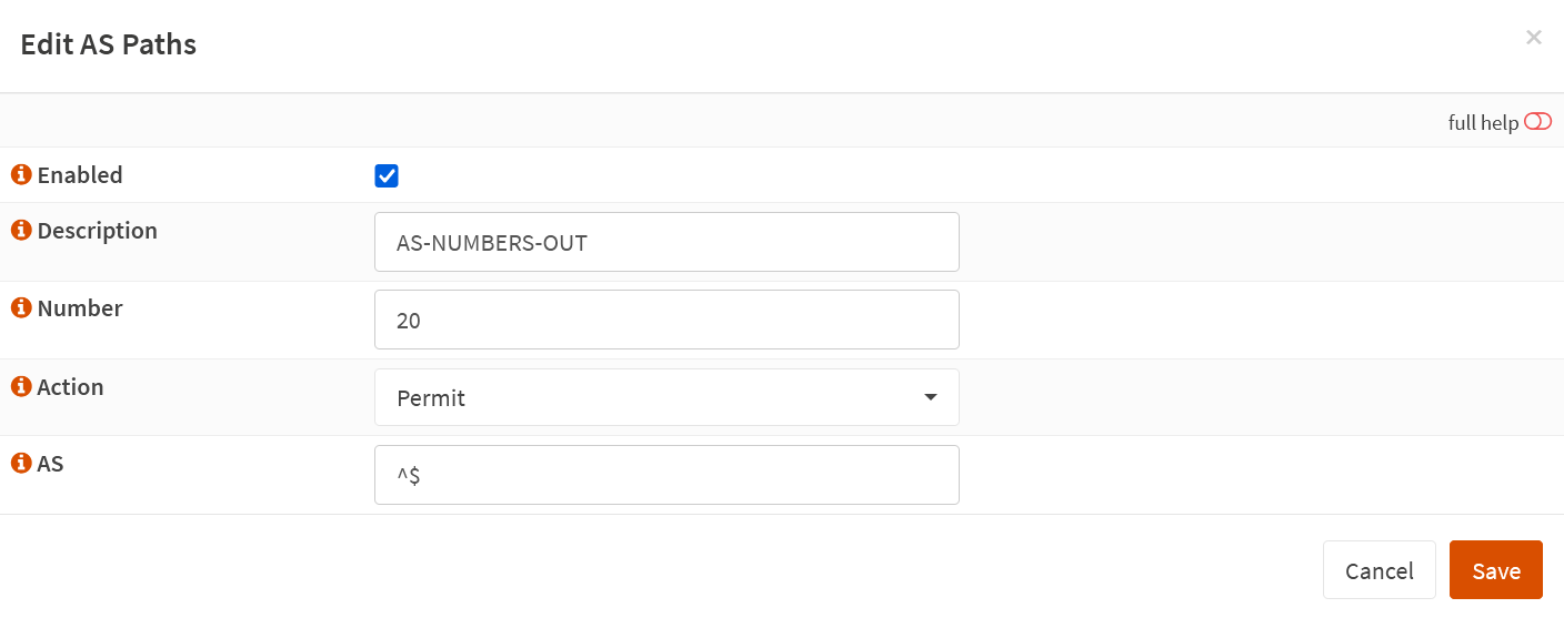
BGP AS Path Filters can be confusing. These filters are regular expressions, and we implement those via route maps you assign to inbound Route maps in the BGP neighbors. But once you wrap your head around them, you’ll be well on your way. I created two AS Path Lists.
The first one is with the AS Numbers we want to allow into our OPNsens ASA router to learn their routes. We give it a description of AS-NUMBERS-IN and the number 10. The only ASN we wish to allow in is AS 65515 (AZURE VPN Gateway). The regular expression ^65515$ (exact match for 65515) achieves that.
The second is the one with the AS Numbers we want to allow out of the OPNsense router so its peers can learn those routes. We give it a description of AS-NUMBERS-OUT and the number 20. The only ASN we want to allow going out to Azure is AS 65521 (OPNsense). That’s what the regular expression ^$ (empty) achieves. Note that in our lab, the OPNsense appliance has no other routers or neighbors connected to it, so here, we get away with only allowing its own ASN.
Route-Maps
Next, we assign the correct AS Path Lists, Prefix Lists, and some extra configurations to the route maps we create here. By applying these route maps to the right BGB neighbors, we can securely route the desired networks and prevent asymmetric routing. For this lab demo, I created four route maps. To do so, navigate to the “Route Maps” tab and click “+” to add one.
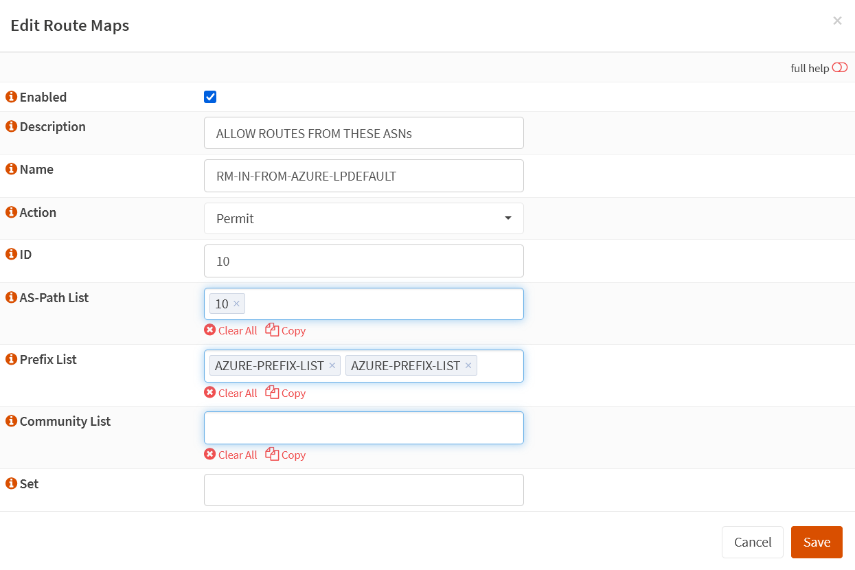
RM-IN-FROM-AZURE-LPDEFAULT
Create a route map ” RM-IN-FROM-AZURE-LPDEFAULT.” Set the action to Permit and give it ID 10. Add the Prefix Lists we created, and finally, add AS-PATH list 10 to it.
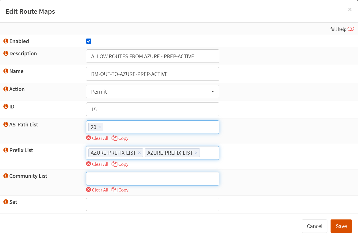
ALLOW ROUTES FROM AZURE – PREP-ACTIVE
Create a route map “ALLOW ROUTES FROM AZURE – PREP-ACTIVE.” Set the action to Permit and give it an ID of 15. Add the Prefix Lists we created, and finally, add AS-PATH list 20 to it.
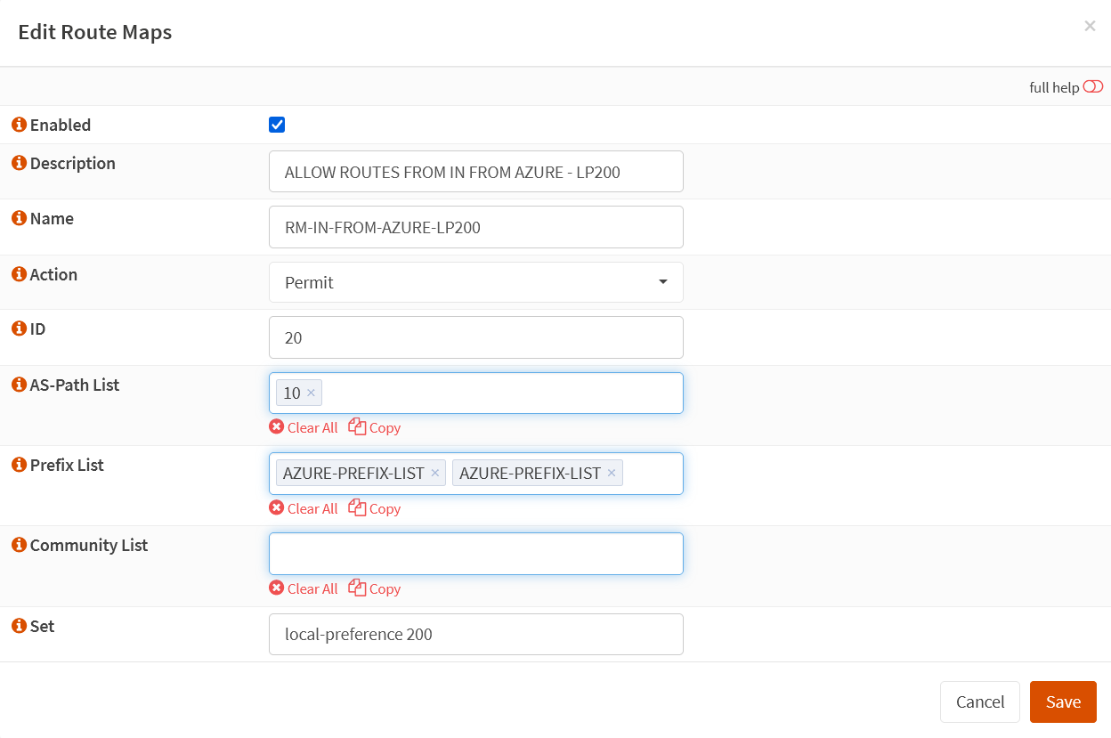
RM-IN-FROM-AZURE-LP200
Create a route map ” RM-IN-FROM-AZURE-LP200″. Set the action to Permit and the ID to 20. Add the Prefix Lists we created, and finally, add AS-PATH list 10 to it.
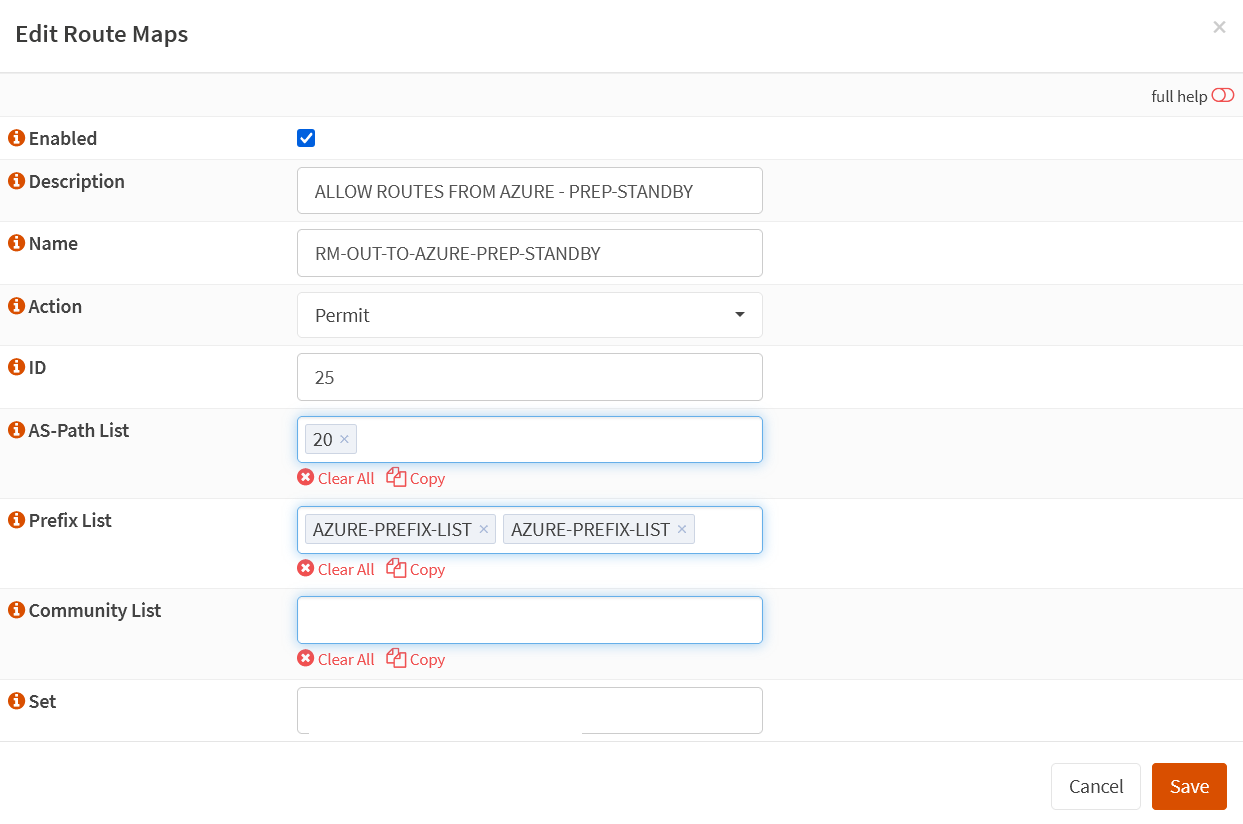
ALLOW ROUTES FROM AZURE – PREP-STANDBY
Create a route map ALLOW ROUTES FROM AZURE – PREP-STANDBY”. Set the action to Permit and the ID to 25. Add the Prefix Lists we created, and finally, add AS-PATH list 20 to it.
We now have four route maps configured, but we must add some extra configurations for as-path prepend and local-preference on two. Why? We are mixing routing and a firewall on the same device combined with how OPNSense does active-active tunnels with BGP. Read on!
Asymmetric Routing
OK, here we go down the rabbit hole! The thing you must realize is that OPNsense combines routing with a Firewall. For BGP to work correctly, we need two public IPs on OPNsense, which introduces the possibility of asymmetric routing of ingress traffic from Azure (ECMP). Routers can handle asymmetry. Firewalls consider asymmetry suspicious and drop the traffic due to TCP state violations. Turning off the firewall and converting OPNsense into a mere router is an option. But one that might only suit a few people who use OPNsense as a firewall.
How does asymmetric routing happen?
The following can happen with our two active-active tunnels with two public IPs on OPNsense with BGP configured and connected to our Azure VPN Gateway. OPNsense sends outgoing traffic toward Azure over Tunnel 0 (which, at that time, is its preferred path by automatic selection). In contrast, the return traffic can arrive on Tunnel 1 (chosen by ECMP on the Virtual WAN HUB routers). That causes an issue as OPNsense is a firewall that drops asymmetrically routed traffic. The rotten thing with this setup is that the return traffic might also go over the same tunnel instance. The latter makes the behavior erratic for those experiencing it. Testing with ping is misleading as it does not carry state and can be allowed through while TCP/443 (HTTPS) traffic drops.
Besides turning off the firewall function, there are two ways of avoiding asymmetric routing with BGP on an on-premises device that requires two public IPs, one for each tunnel in an active-active setup.
Option 1: Use “as-path prepend” and “local-preference” to avoid asymmetric routing.
We use “as-path prepend” to ensure incoming to OPNsense routes via the tunnel for Instance 0. We also use “local-preference” to ensure the outgoing traffic. The result is that incoming and outgoing traffic prefers the tunnel for Instance 0, which avoids asymmetric routing! The drawback here is that we have one “standby” path; as such, it is not genuinely active-active, but it beats dropped traffic. So, how do we do this?
1. We do this by configuring “as-path prepend” to ensure incoming traffic to the on-prem devices favors tunnel instance 0.
route-map RM-OUT-TO-AZURE-PREP-STANDBY permit 10
match ip address prefix-list prefix-any
set as-path prepend 65521 65521
 We assign RM-OUT-TO-AZURE-PREP-STANDBY to the BGP neighbor configuration for Instance 0 and NOT to Instance 1, so it becomes the preferred path, and Instance 1 becomes the backup path. OPNsense BGP prefers one path, but we need to make this deterministic. That is what we just did. See the next heading about configuring BGP neighbors.
2.We use “local-preference” to ensure outgoing traffic from the on-prem device prefers the same Instance 0. 200 is higher than the default 100, so it is preferred.
route-map RM-IN-FROM-AZURE permit 10
match ip address prefix-list prefix-any
set local-preference 200
We assign RM-IN-FROM-AZURE-LP200 to the BGP neighbor configuration for Instance 1, NOT to Instance 0. Adding the ASNs for the OPNsense device makes this path longer, which means Instance 0 becomes the preferred path. If that path goes down, Instance 1 is the backup path. See the next heading about configuring BGP neighbors.
Option 2: Use only one tunnel or move to static or policy bases routing
Ah, that might work, but we have already established that we don’t have failover in this scenario. While that is a fix that works, it is not a solution. You’re better off with static or policy-based routing instead of BGP. You’ll have high availability over active-active tunnels over one Public IP interface on your OPNsense, which we discussed in Part 1 and Part 2.
Neighbors
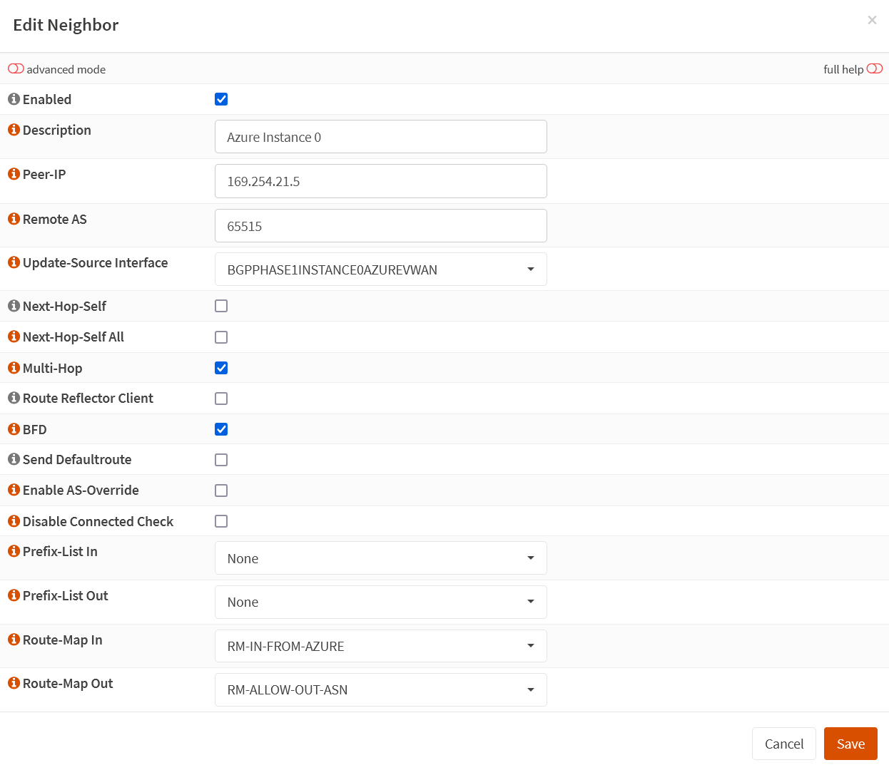
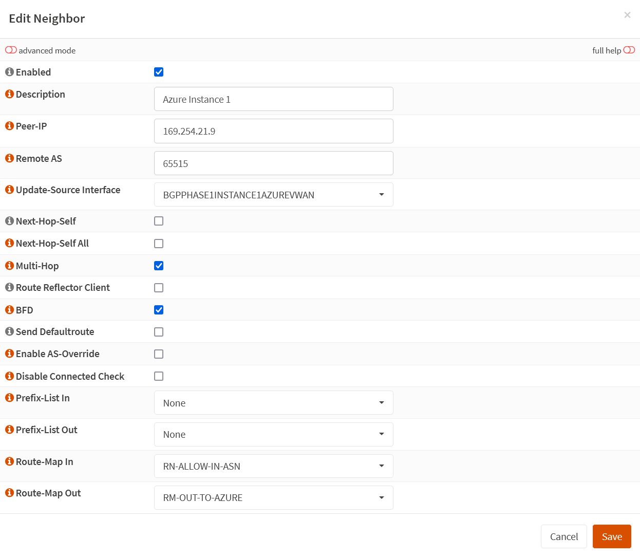
I created two neighbors. One for each of both tunnels (Instance 0 and Instance 1). Navigate to the neighbors tab and click “+” to add a neighbor. Fill out the following information.
Enabled: checked
Description: Azure Instance 0
Peer-IP: 169.265.21.5
Remote AS: 65515
Update-Source Interface: BGPPHASAE1INSTANCE0AZUREWAN
Next-Hop-Self: unchecked
Next-Hop-Self All: unchecked
Multi-Hop: checked
Route Reflector Client: unchecked
BFD: checked
Send Defaultroute: unchecked
Enable AS-Override: unchecked
Disable Connected Check: unchecked
Prefix-List In: None
Prefix-List Out: None
Route-Map In: RM-IN-FROM-AZURE
Route-Map Out: RM-ALLOW-OUT-ASN
Navigate to the neighbors tab and click “+” to add a neighbor. Fill out the following information.
Enabled: checked
Description: Azure Instance 1
Peer-IP: 169.265.21.9
Remote AS: 65515
Update-Source Interface: BGPPHASAE1INSTANCE1AZUREWAN
Next-Hop-Self: unchecked
Next-Hop-Self All: unchecked
Multi-Hop: checked
Route Reflector Client: unchecked
BFD: checked
Send Defaultroute: unchecked
Enable AS-Override: unchecked
Disable Connected Check: unchecked
Prefix-List In: None
Prefix-List Out: None
Route-Map In: RM-ALLOW-IN-ASN
Route-Map Out: RM-OUT-TO-AZURE
Below, you’ll find the overview of the Neighbors configuration.
Configure BFD
Using BFD is optional. Actually, with an Azure VPN Gateway and BGP, BFD is unsupported. It won’t work. But I am still adding it here in case it becomes supported or when you are using this guide for a similar setup between OPNsense devices. Configuring BSD is easy. Navigate to Routing/BFD in the left navigation pane. Go to the “General” tab and check the box to enable it.
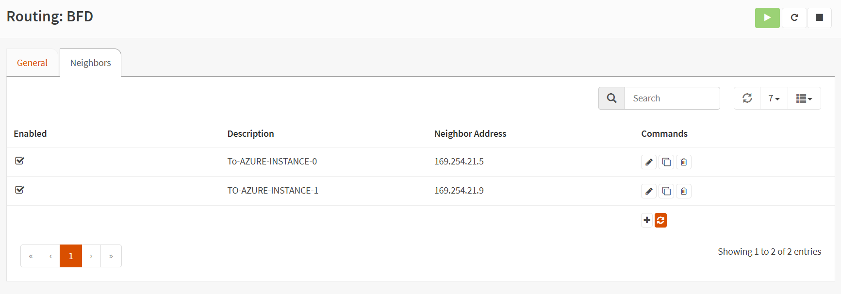
Select the “Neighbors” tab and add two neighbors. One is for Instance 0, which points to remote BGP-Peer-IP 169.254.21.5, and one is for Instance 1, which points to remote BGP-Peer-IP 169.254.21.9.
So you end up with these to BFD neighbors defined.
Remember, this shows how to do it, nothing else, as it does not work on the Azure side for now. So, disable or remove it to avoid issues or confusion.
Results
When you configured everything correctly on both sides, in OPNsense and Azure, you should see the tunnels active in the VPN/IPsec/Status Overview.
Take a look at the VPN/IPsec/Security Association Database. Note our custom IPsec configuration in use. 
Next, you can check the VPN/IPsec/Security Policy Database. Note the route for IPv4/IPv6 going over the public IPs of both instances in both directions. 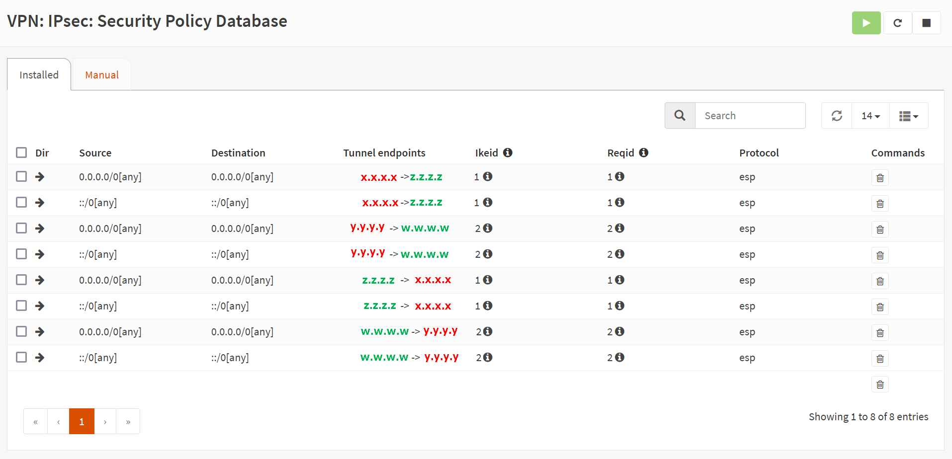
Finally, check the VPN/IPsec/Virtual Tunnel Interfaces where you see both tunnels established.
Under Routing/Diagnostics/General/Ipv4 Routes, you can see the routing table, populated with BGP Learned routes to your preferred Instance as a gateway.
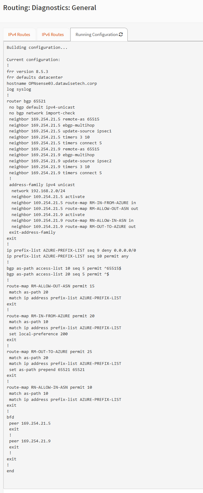
In Under Routing/Diagnostics/General/Running configuration, you can check the CLI for your setup.
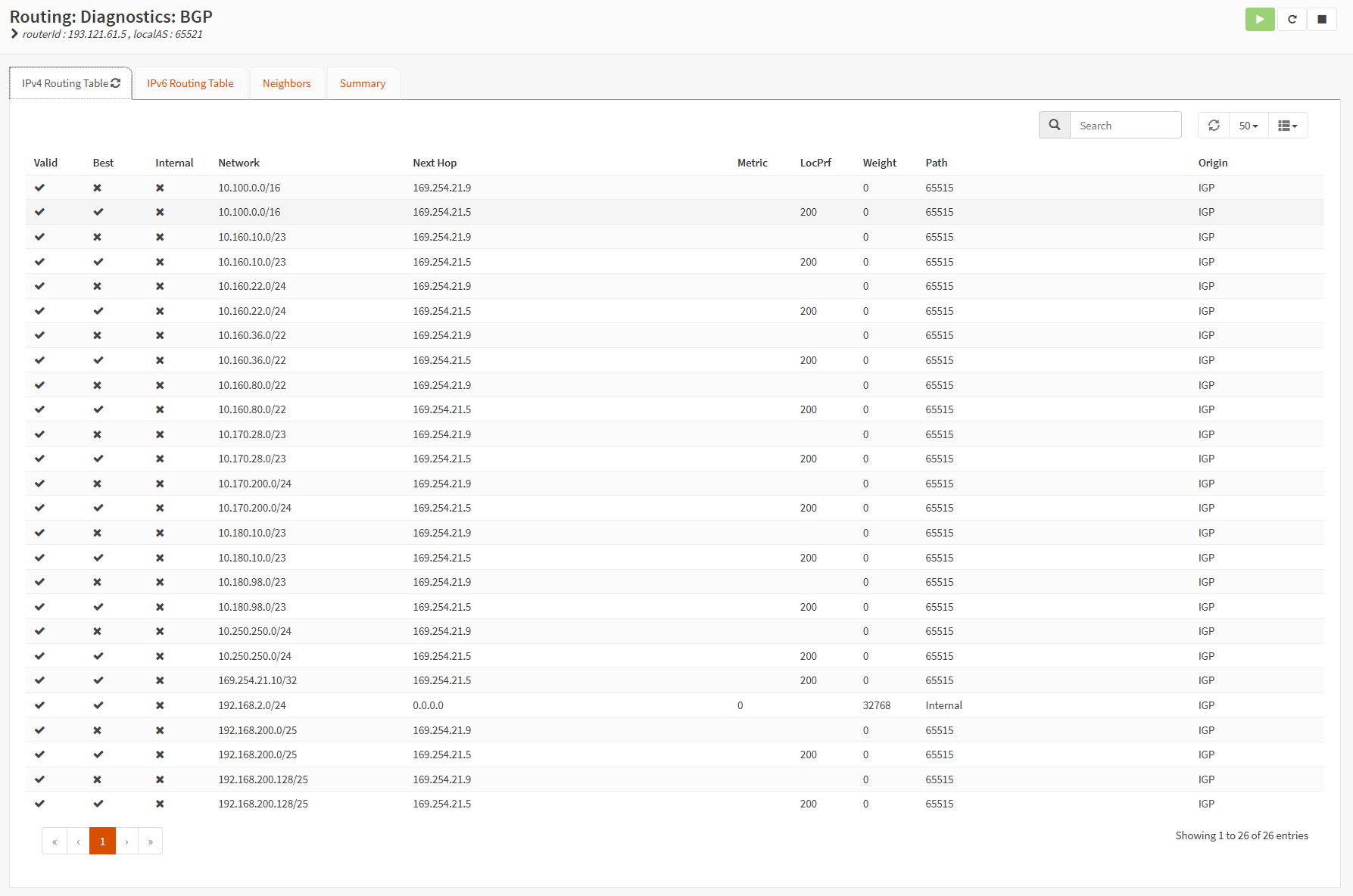
Move on to the Routing/Diagnostics/BGP/IPv4 Routing Table tab, where you can see the result of our config. Note LOcPref that is set to 200 for Instance 1.
On Routing/Diagnostics/BGP/Neighbors, you can find the status and stats about your NGP neighbors. 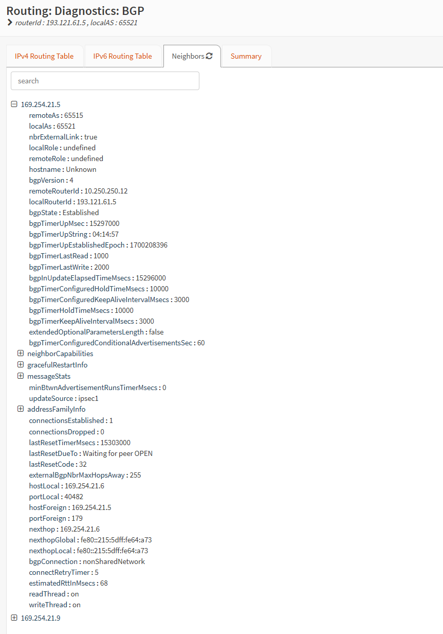
All components have logging, so if you have issues, check those logs and double-check all settings on the OPNsense and Azure side.
Testing!
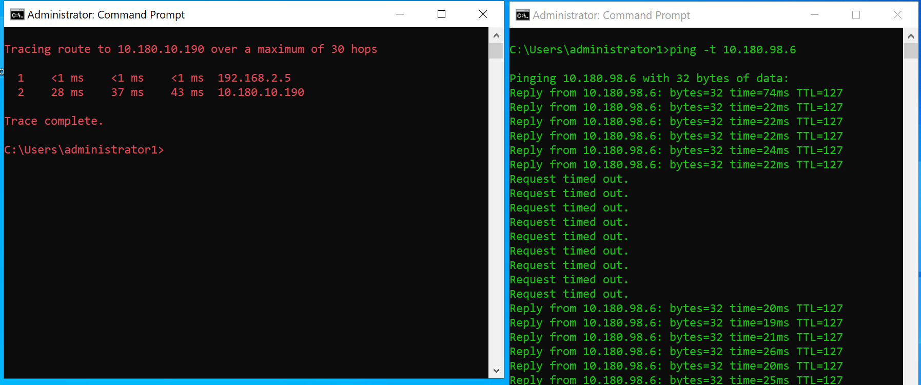
With two tunnels set up for the active-active Azure site-to-site VPN tunnels, check some pings in both directions. If that works, verify that failover does its job by testing it. I disconnected the WAN NIC on OPNsense that serves Instance 0 (the preferred one due to our setup). With that path gone, Instance 1 becomes active.
You should see about a dozen dropped pings before the BGP config comes up for Instance 1 with the correct routes, but then you are back in business. Communication should all flow over the tunnel for Instance 1.
When the WAN interface for Instance 0 becomes available again, traffic returns to flowing over that preferred tunnel instance 0. But that is one or a maximum of two dropped pings.
Test your workloads (HTTPS, SQL, AD, DNS, …). Pings alone are insufficient to determine if any asymmetric routing is going on. While doing tests, look at the logs, diagnostics, and status pages. Get a feel for how it behaves and understand why. Do not put anything into mission-critical production environments if you don’t fully understand the configuration and know the behavior.
That great learning experience serves you well, helping you build better solutions and become a true expert. One that cuts through the marketing BS of everything is excellent and easy and can make an environment run well and reliably in production.
Learning moments
You need two public IPs to establish the two active-active tunnels BGP on the same firewall/router appliance. That is not unusual. CISCO ASA and pfSense, for example, are similar.
For complete redundancy/high availability, I need to use two appliances, but note that OPNsense only supports an active-passive setup.
In an Azure Virtual WAN virtual hub, a site-to-site VPN gateway provisions in active-active mode. While you can connect only one tunnel, the expectation is to use (at least) two separate tunnels from on-premises devices that terminate on different instances 0 and 1.
With policy-based (part 1) and static route-based (part 2), you can achieve high availability via two tunnels over a single public IP. Sure, you experience reconnects, but still, it is high availability. But always test your assumptions and watch out for asymmetric routing issues there. If you have only one active tunnel with BGP dynamic route-based site-to-site VPN to the Azure VWAN, you suffer downtime during patching and other maintenance. BGP sessions cannot move across instances. BGP with a single tunnel always requires manual reconfiguration. As a result, this needs to be revised, and static routing is the better choice if you only have one public IP address. That is why we went through the effort of provisioning a second WAN interface with a second public IP address. As a result, we had to deal with asymmetric routing concerns.
Conclusion
I have shown you how to configure a route-based site-to-site VPN with dynamic routing via BGP In OPNsense to an Azure VWAN VPN Gateway. It took me a while to get this working, so I hope this article helps you out by saving time figuring out how to do it. In part 1, you can learn about policy-based configuration, and in part 2, I discuss route-based with static routing.
BGP configuration can initially seem daunting, but once you test the concepts in the lab, you soon learn to configure, test, and troubleshoot such setups. That’s why I put in the effort into writing this article. I use OPNsense in the lab as it gets frequent updates and has a clean, easy-to-follow user interface. The benefit OPNsense has over Microsoft RRAS is that it also has a firewall. Learning about configuring firewalls and routing using OPNsense is excellent for educational purposes. The experience prepares you for configuration challenges in your work and production environments.


