StarWind Virtual SAN: Feature Configuration Guide for Scale Out on VMware vSphere [ESXi]
- March 12, 2019
- 12 min read
- Download as PDF
Annotation
Relevant products
StarWind Virtual SAN (VSAN)
Purpose
This document outlines how to reconfigure existing 2-node Hyperconverged setup with VMware vSphere by adding an additional node into configuration and getting a 3-node configuration with 2-way active-active StarWind VSAN replication. It’s assumed that StarWind HA devices (DS1 and DS2) and corresponding datastores are already created. One more StarWind HA device will be added as a part of reconfiguration and corresponding datastore (DS3) will be created in VMware vSphere.
Audience
This technical guide is intended for storage and virtualization architects, system administrators, and partners designing virtualized environments using StarWind Virtual SAN (VSAN).
Expected result
The end result of following this guide will be a fully configured 3-node high-availability ESXI-based setup.
Prerequisites
StarWind Virtual SAN system requirements
Prior to installing StarWind Virtual SAN, please make sure that the system meets the requirements, which are available via the following link:
https://www.starwindsoftware.com/system-requirements
Recommended RAID settings for HDD and SSD disks:
https://knowledgebase.starwindsoftware.com/guidance/recommended-raid-settings-for-hdd-and-ssd-disks/
Please read the StarWind Virtual SAN Best Practices document for additional information:
https://www.starwindsoftware.com/resource-library/starwind-virtual-san-best-practices
Solution diagram
The idea behind scale-out is to grow both storage and compute power by adding additional nodes instead of adding disks, CPUs, NICs, or RAM to individual systems.
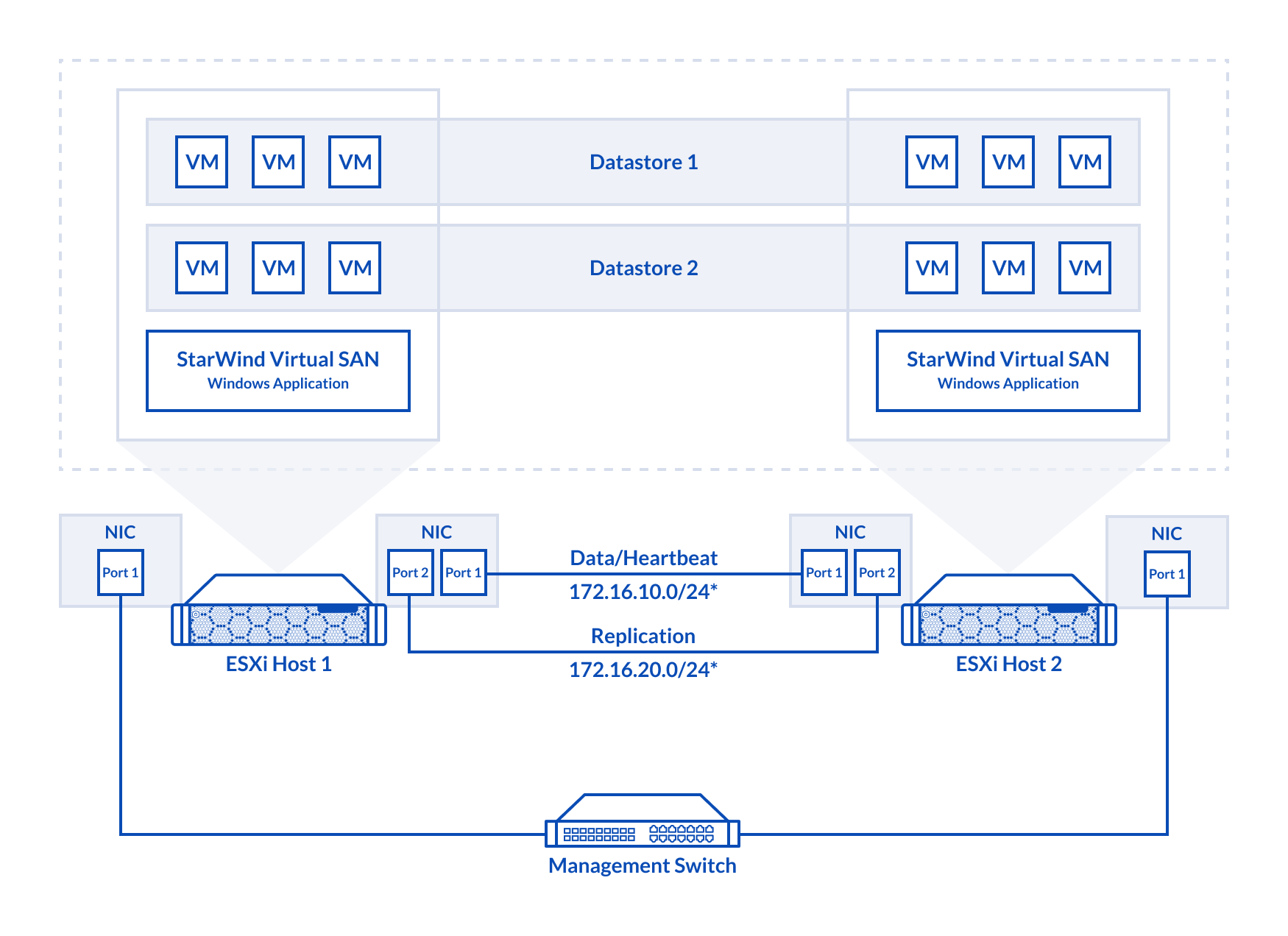
The diagram below illustrates the network and storage configuration of the 2-node Hyperconverged Scenario with VMware vSphere. The article on how to deploy a 2-node Hyperconverged Scenario with VMware vSphere could be found at the link below:
https://www.starwindsoftware.com/resource-library/starwind-virtual-san-vsan-configuration-guide-for-vmware-vsphere-esxi-7-vsan-deployed-as-a-controller-virtual-machine-cvm-using-web-ui/
The diagram below illustrates the resulting network and storage configuration of the 3-node deployment with 2-way active-active StarWind VSAN replication:
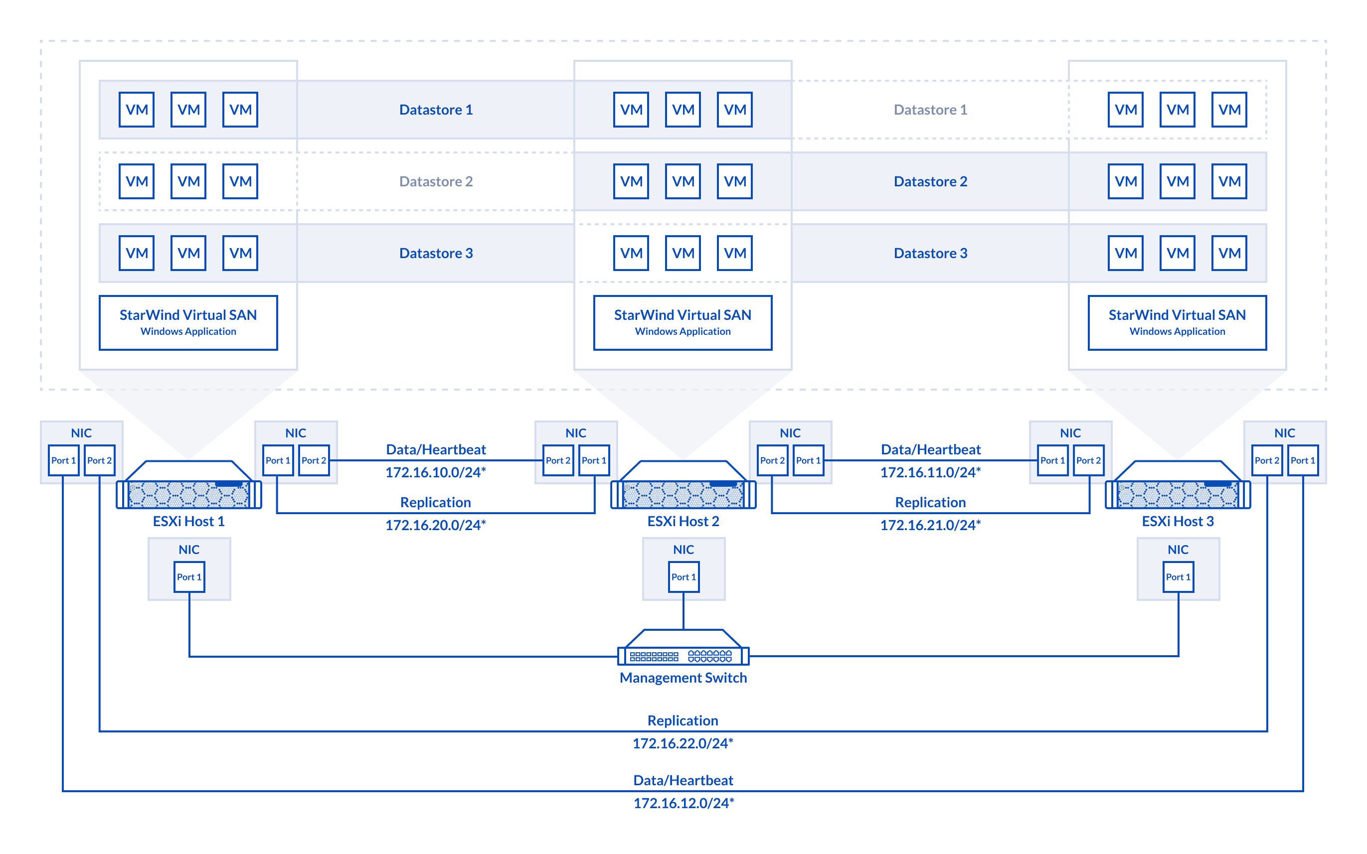
1. ESXi hypervisor should be installed on each host.
2. StarWind VSAN should be installed on the Windows Server operating system deployed as VM on each host.
3. The hosts should have additional network interfaces to the connection the Host 2 to the Host 3 and the Host 1 to the Host 3 for iSCSI and Heartbeat traffic.
4. On each node, network interfaces to be used for Synchronization and iSCSI/StarWind heartbeat should be in different subnets and connected directly according to the network diagram above. Here, the 172.16.10.x, 172.16.11.x, 172.16.12.x subnets are used for the iSCSI/StarWind heartbeat traffic, while the 172.16.20.x, 172.16.21.x, 172.16.22.x subnets are used for the Synchronization traffic.
NOTE: Do not use ISCSI/Heartbeat and Synchronization channels over the same physical link. Synchronization and iSCSI/Heartbeat links can be connected either via redundant switches or directly between the nodes.
Replacing Partner for DS2 Virtual Disk
1. Open StarWind Management Console and add the third StarWind server(SW3), which was previously deployed.

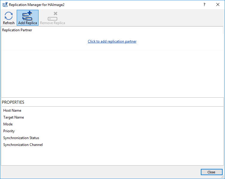
2. Open Replication Manager for DS2 device on the second StarWind node.

3. Click Remove Replica. The replica to the first node (SW1) will be removed.

4. Click Add Replica.
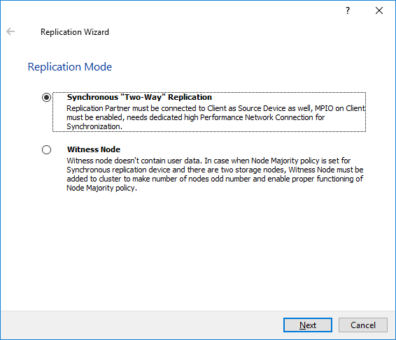
5. Select Synchronous “Two-Way “Replication and click Next.
6. Enter Host Name or IP Address of the third StarWind node.
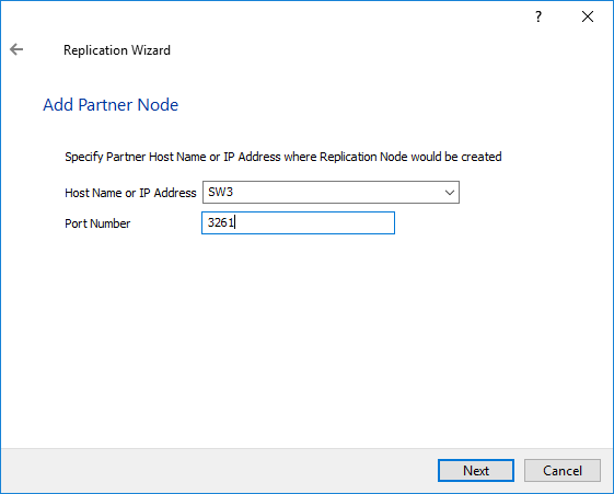
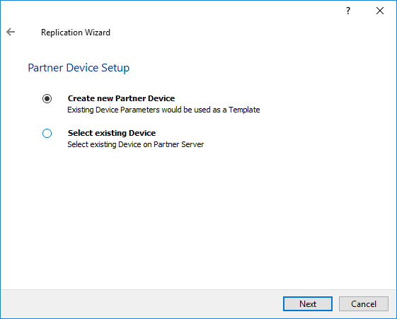
7. Select Create new Partner device.
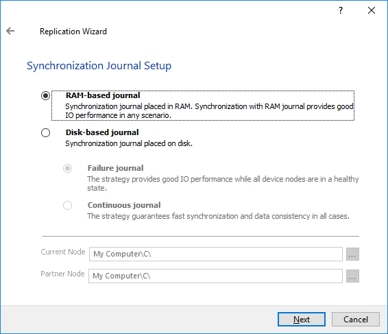
8. Select Synchronization Journal Strategy and click Next.
NOTE: There are several options – RAM-based journal (default) and Disk-based journal with failure and continuous strategy, that allow to avoid full synchronization cases.
RAM-based (default) synchronization journal is placed in RAM. Synchronization with RAM journal provides good I/O performance in any scenario. Full synchronization could occur in the cases described in this KB: https://knowledgebase.starwindsoftware.com/explanation/reasons-why-full-synchronization-may-start/
Disk-based journal placed on a separate disk from StarWind devices. It allows to avoid full synchronization for the devices where it’s configured even when StarWind service is being stopped on all nodes.
Disk-based synchronization journal should be placed on a separate, preferably faster disk from StarWind devices. SSDs and NVMe disks are recommended as the device performance is defined by the disk speed, where the journal is located. For example, it can be placed on the OS boot volume.
It is required to allocate 2 MB of disk space for the synchronization journal per 1 TB of HA device size with a disk-based journal configured and 2-way replication and 4MB per 1 TB of HA device size for 3-way replication.
Failure journal – provides good I/O performance, as a RAM-based journal, while all device nodes are in a healthy synchronized state. If a device on one node went into a not synchronized state, the disk-based journal activates and a performance drop could occur as the device performance is defined by the disk speed, where the journal is located. Fast synchronization is not guaranteed in all cases. For example, if a simultaneous hard reset of all nodes occurs, full synchronization will occur.
Continuous journal – guarantees fast synchronization and data consistency in all cases. Although, this strategy has the worst I/O performance, because of frequent write operations to the journal, located on the disk, where the journal is located.
9. Click Change Network Settings. Specify the interfaces for Synchronization and Heartbeat channels. Click OK. Then click Next.

10. Click OK to return to Network Option for Synchronization Replication. Click Next.
11. Click Create Replica.
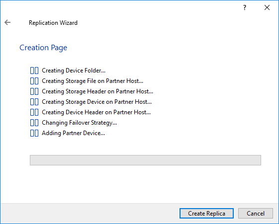
12. After creation, click Finish to close the Replication Wizard. The result should look as shown in the screenshot below.

Creating Virtual Disk DS3
1. Select SW3 server and open Add Device wizard by right-clicking the StarWind server and selecting Add Device (advanced) from the shortcut menu or by clicking the Add Device (advanced) button on the toolbar.
2. Once Add Device wizard appears, follow the instructions to complete the creation of a new disk, which will be replicated to SW1 server.
3. Select Hard Disk Device as the type of a device to be created. Click Next to continue.
4. Select Virtual Disk. Click Next to continue.
5. Specify virtual disk location and size.

6. Specify Virtual Disk Options and click Next to continue.
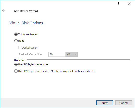
NOTE: Sector size should be 512 bytes when using ESXi.
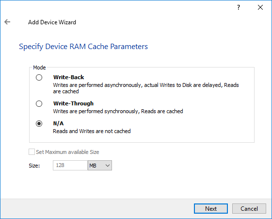
7. Define the RAM caching policy and specify the cache size in the corresponding units if required.
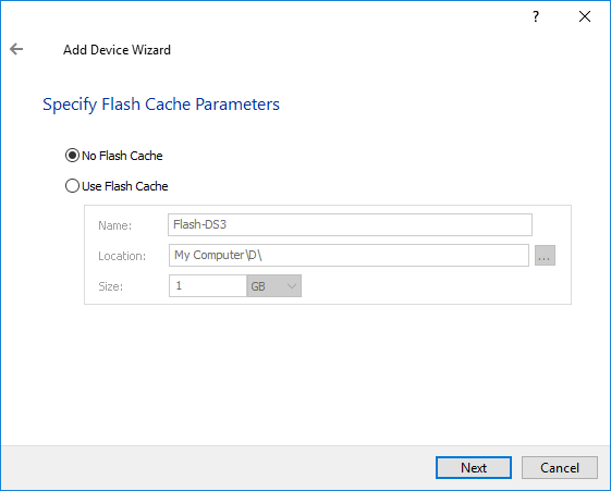
8. Define the Flash caching policy and the cache size. Click Next to continue.
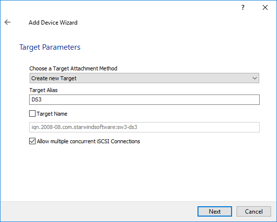
9. Specify Target Parameters. Select the Target Name checkbox to enter a custom name of the target if required. Otherwise, the name will be generated automatically in accordance with the specified target alias. Click Next to continue.
10. Click Create to add a new device and attach it to the target and Finish to close the wizard.
11. Right-click on the recently created device and select Replication Manager from the shortcut menu.

12. Click Add replica and select Synchronous “Two-Way Replication”.

13. Specify partner Host Name (SW1) or IP address and Port Number.
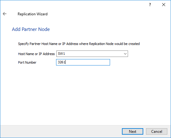
14. Select Create new Partner Device and click Next.
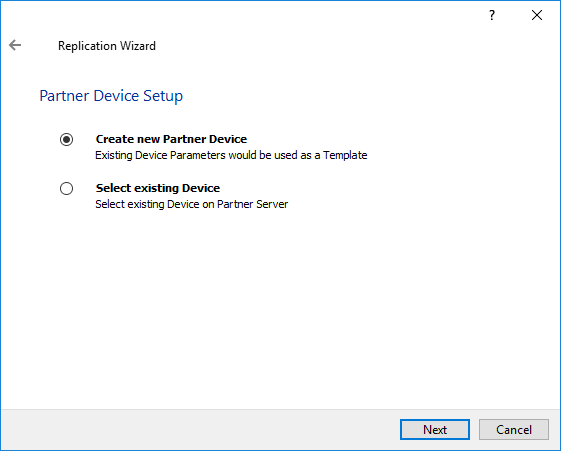
15. Select Synchronization Journal Strategy and click Next.
NOTE: There are several options – RAM-based journal (default) and Disk-based journal with failure and continuous strategy, that allow to avoid full synchronization cases.
RAM-based (default) synchronization journal is placed in RAM. Synchronization with RAM journal provides good I/O performance in any scenario. Full synchronization could occur in the cases described in this KB: https://knowledgebase.starwindsoftware.com/explanation/reasons-why-full-synchronization-may-start/
Disk-based journal placed on a separate disk from StarWind devices. It allows to avoid full synchronization for the devices where it’s configured even when StarWind service is being stopped on all nodes.
Disk-based synchronization journal should be placed on a separate, preferably faster disk from StarWind devices. SSDs and NVMe disks are recommended as the device performance is defined by the disk speed, where the journal is located. For example, it can be placed on the OS boot volume.
It is required to allocate 2 MB of disk space for the synchronization journal per 1 TB of HA device size with a disk-based journal configured and 2-way replication and 4MB per 1 TB of HA device size for 3-way replication.
Failure journal – provides good I/O performance, as a RAM-based journal, while all device nodes are in a healthy synchronized state. If a device on one node went into a not synchronized state, the disk-based journal activates and a performance drop could occur as the device performance is defined by the disk speed, where the journal is located. Fast synchronization is not guaranteed in all cases. For example, if a simultaneous hard reset of all nodes occurs, full synchronization will occur.
Continuous journal – guarantees fast synchronization and data consistency in all cases. Although, this strategy has the worst I/O performance, because of frequent write operations to the journal, located on the disk, where the journal is located.

16. Click Change Network Settings.

16. Click Create Replica.
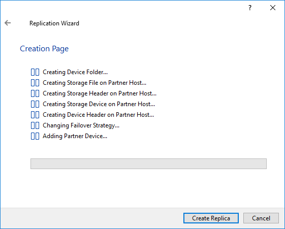
17. The added devices are seen in the StarWind Console.

Creating Datastores
1. Open the Storage tab on one of the hosts and click on New Datastore.
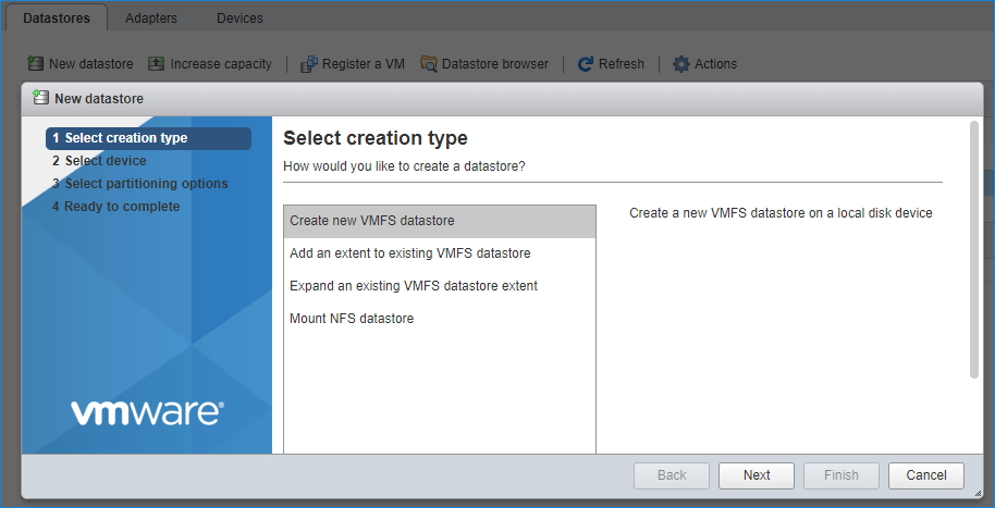
2. Specify the datastore name, select the previously discovered StarWind device, and click on Next.
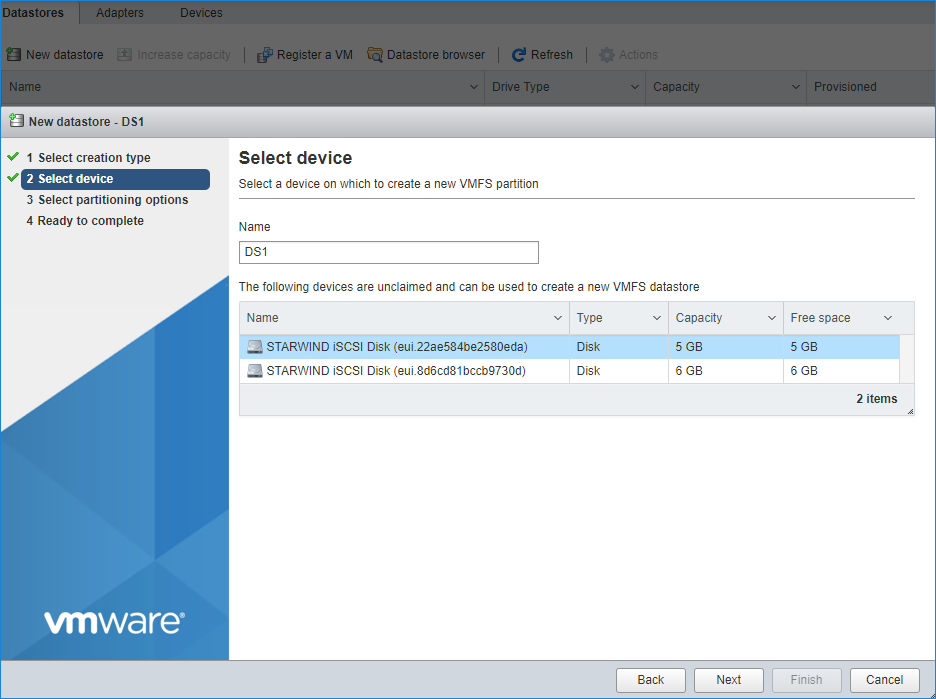
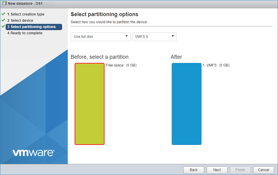
3. Enter datastore size. Click on Next.
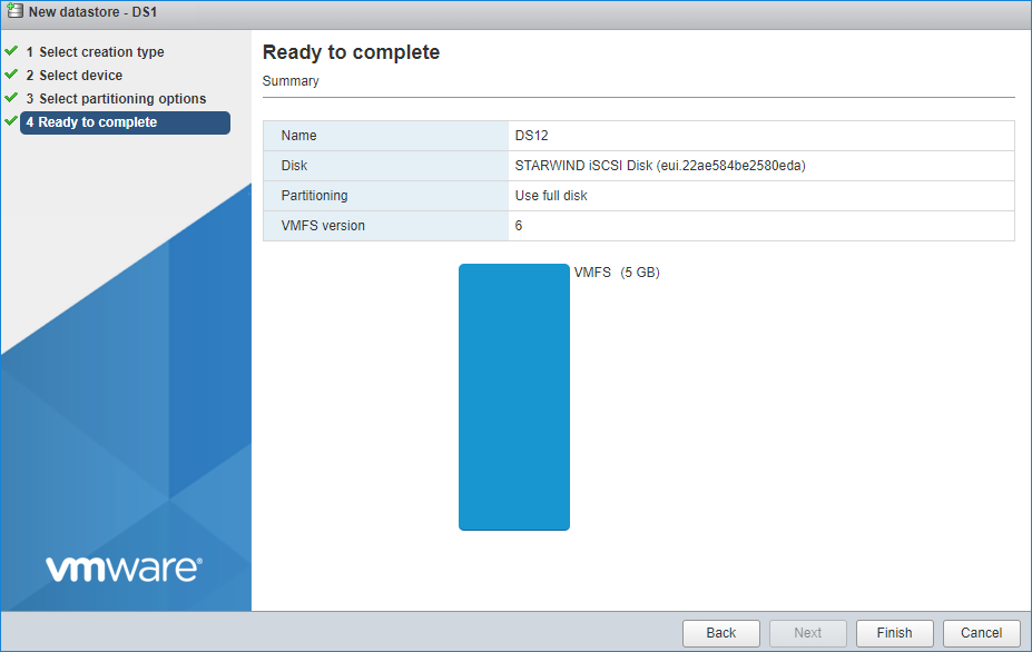
4. Verify the settings. Click on Finish.
5. Add another datastore (DS2) in the same way but select the second device for it.
6. Verify that storage (DS1, DS2) is connected to both hosts. Otherwise, rescan the storage adapter.

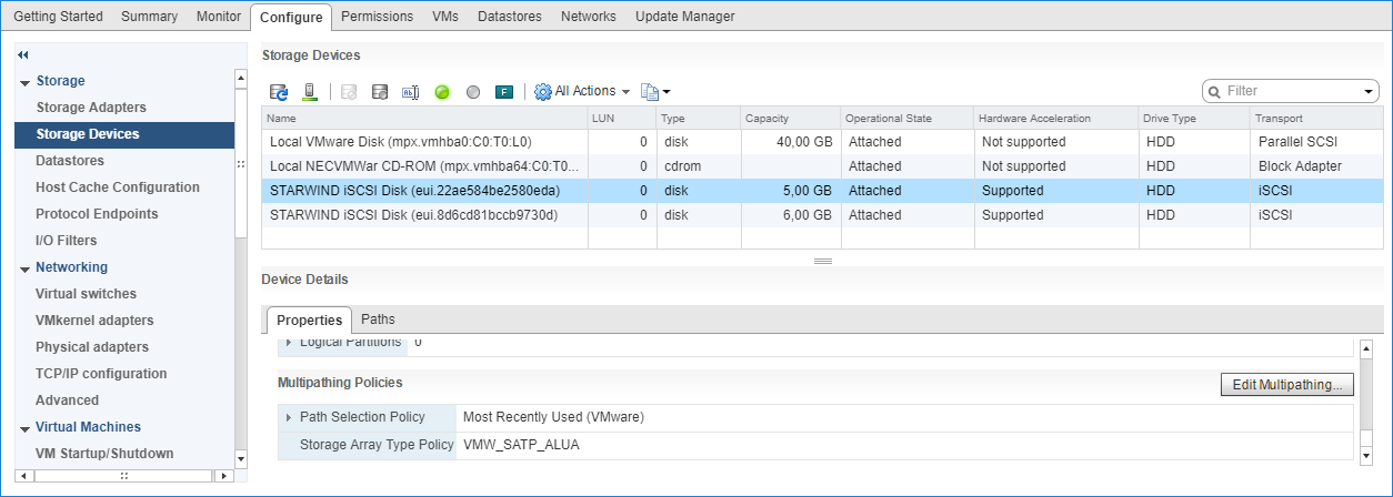
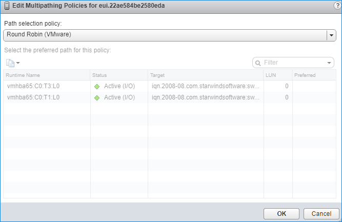
7. Path Selection Policy changing for Datastores from Most Recently Used (VMware) to Round Robin (VMware) has been already added into the Rescan Script, and this action is performed automatically. For checking and changing this parameter manually, the hosts should be connected to vCenter.
8. Multipathing configuration can be checked only from vCenter. To check it, click the Configure button, choose the Storage Devices tab, select the device, and click on the Edit Multipathing button.
Performance Tweaks
1. Click on the Configuration tab on all of the ESXi hosts and choose Advanced Settings.
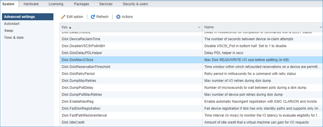
2. Select Disk and change the Disk.DiskMaxIOSize parameter to 512.
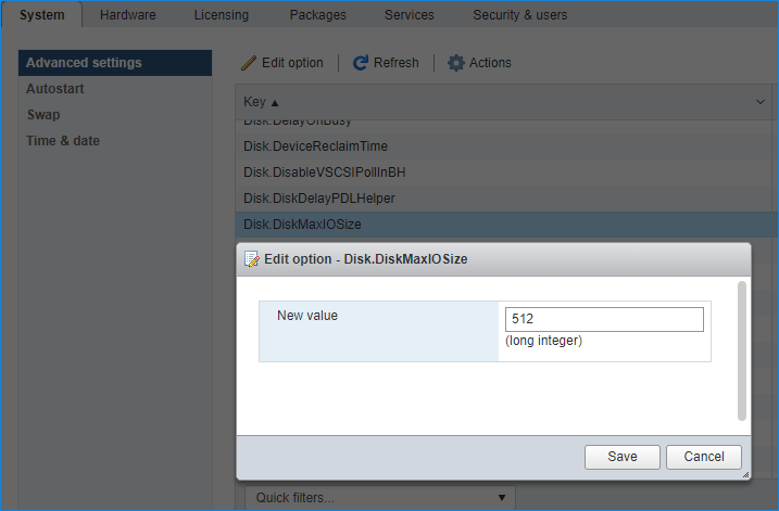
NOTE: Changing Disk.DiskMaxIOSize to 512 might cause startup issues with Windows-based VMs, located on the datastore where specific ESX builds are installed. If the issue with VMs start appears, leave this parameter as default or update the ESXi host to the next available build.
NOTE: In certain cases, in Virtual Machine, Windows event log may report an error similar to “Reset to device, \Device\RaidPort0, was issued”. Check this KB acticle for a possible solution.
Conclusion
Following this guide, the existing 2 node ESXI -based cluster was reconfigured and the 3d node was added. As a result, the cluster was extended and got more available space for storing highly available virtual machines.

